


 tel:+86-18825224069
 email:
 address:201, Factory 6, Longhui Industrial Park, Fuqiao 3rd District, Xinhe Community, Fuhai Street, Baoan District, Shenzhen china
The working principle and working method of the wave clipping detector
Release date:2022-02-24 17:35:14 Number of views:0
A clipping detector is an ideal tool you need if you're having trouble detecting when clipping occurs in your audio unit. Since a lot of clipping can happen in your amplifier before you notice, it makes a clipping detector very important. Without it, you won't be able to detect clipping problems early. Additionally, there are a lot of clipping detector designs available online, so you might get confused about making the ideal choice. Thankfully, we're here to make things more straightforward for you. So, in this article, we'll look in-depth at a clipping detector, how it works, and how to make an easy one for your PCB board. Let's kick-off!
What is a Clipping Detector?
Essentially, the clipping detector is an accessory that helps you detect clipping in mixers, amplifiers, and various other audio units. Clipping detectors can also work as portable circuits that signal when clipping occurs on the output waveform of an audio stage. 
Mixers
In addition, clipping occurs when an output waveform approaches the allowed highest peak-to-peak voltage but drops and overloads after going beyond its limit. Thus, clipping detectors can help you avoid terrible audio distortions from generating through your audio equipment. Hence, the clipping detector circuit will show you when a signal you're testing has clipped. As a result, the detector becomes helpful in sorting out annoying distortion issues in amplifiers.
What Causes Clipping?
Indeed, clipping is a type of waveform distortion that only happens when you push an audio unit into overdrive—making it work beyond its maximum limit. In this overdriven state, the audio unit generates an output current or voltage that's way higher than it can handle. As a result, clipping occurs. For instance, if your clipping happens in your loudspeaker after kicking it into overdrive, you can usually hear it as distortions or breaks in the produced sound. If you leave that loudspeaker in its clipping state, it could potentially overheat and damage the speaker. Thankfully, many of these speakers come equipped with circuits that prevent clipping.
Loudspeaker
How does a Clipping Detector Work?
There are two ways a clipping detector work:
First Clipping Detector Method
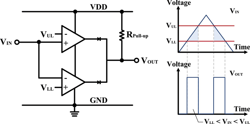
Specifically, the window comparator is majorly responsible for working a clipping detector.
Window Comparator Circuit
Source: Researchgate Plus, the window comparator consists of two op-amps which make up one IC1. So, it allows the detector to give accurate and symmetrical readings whenever the signal under test reaches a negative or positive peak value. But that's not all. The diodes in the circuit also help mix the op-amps' output, while the capacitor and resistor smooth out the signal. Thus, the transistor is responsible for feeding a positive pulse to the LED driver, and another capacitor makes it possible to detect short clippings by adding a slight output delay.
Second Clipping Detector Method
Alternatively, your detector will activate whenever your audio unit reaches the maximum point of the output signal voltage. But, it all depends on the audio unit's supply voltage. Additionally, if the produced signal reduces before it approaches the maximum limit, the clipping detector will not activate. However, it can detect instant clippings at any time.
The Working Process of the Clipping Detector
The clipping detector uses the instant power supply voltage value as a final reference point. Hence, it constantly measures the output signal against the supply voltage with the help of its transistors. Although there are several clipping detector circuits, most of them depend on an attenuated output signal (reduced version). And the course supplies it to a compatible comparator circuit. However, this principle works better with a constant primary voltage and perfectly regulated power supply. Sadly, the supply voltage of any audio unit varies from minute to minute and even hour to hour. In the next section, we'll discuss how to make a clipping detector, which will only depend on one factor; "How close the output signal is to the supply voltage at any time." So, when there's a change in the supply voltage, the detector will change with it. Plus, such circuits can detect sneaking short clippings that jump across the threshold for detection.
How Do You Make a Clipping Detector?
Here, we have a simple clipping detector that also uses a simple method of operation explained above. The purpose of the "External" terminal on the circuit diagram below is to allow any additional channels to use the same pulse stretch circuit. For this reason, it's possible to configure multiple clipping detectors while using one clipping LED. However, each sensor uses a different amp supply voltage. So, here's the diagram of the circuit we'll be working with: 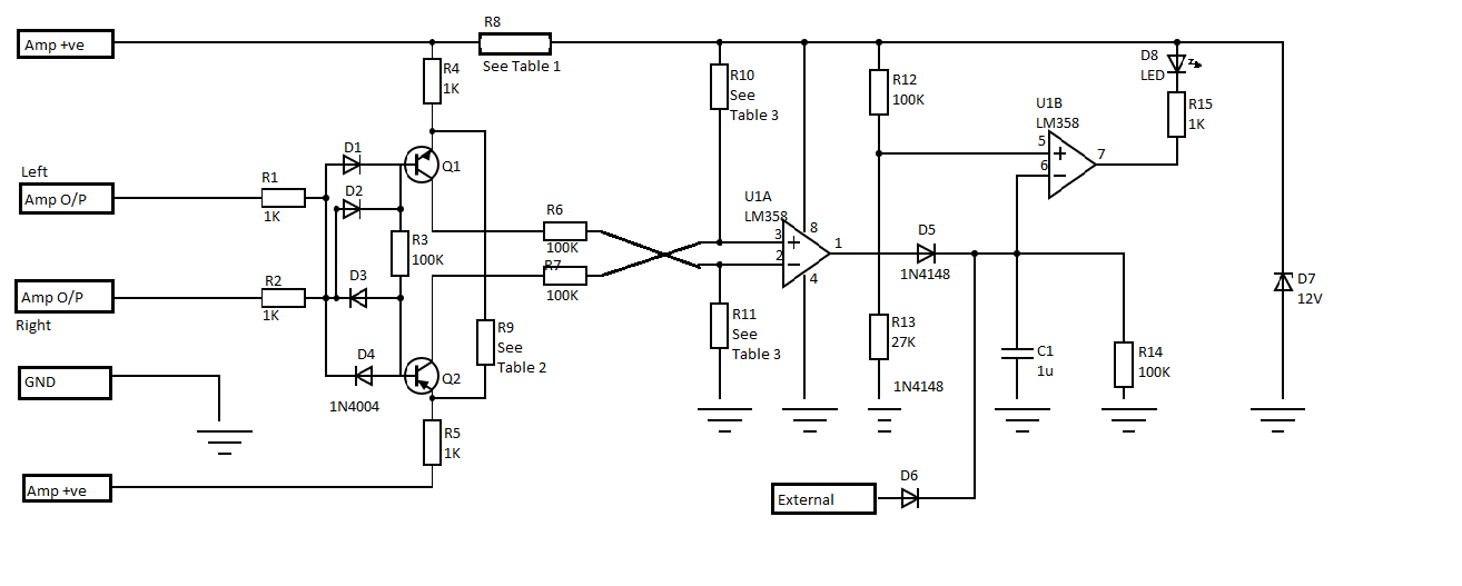
Circuit Diagram
Components
R1= 1K
R2= 1K
R3= 100K
R4, R5= 1K
R6, R7= 100K
R8= Dropper resistor
Dropper Resistor Source: Pixlr
R9= Clipping reference resistor
R10, R11= Opamp input resistors
R12= 100K
R13= 27K
R14= 100K
R15= 1K
D1, D2, D3, D4= 1N4004
D5, D6=1N4148/1N4148
D7=ZD 12V
D8+= LED
U1A/U1B= LM358
Q1, Q2=PNP/NPN
Steps
Assemble your circuit on a PCB with good quality or a standard board

You can power your circuit with a 9V PP3 battery
Lastly, calibrate the course with the POT R5
Design Considerations
The two transistors (Q1 and Q2) detect these circuits. While the operation of Q1 sees the positive peak, Q2's function recognizes the negative peak. When the audio unit is operating normally with no clipping, Q1 remains up. Its design allows the transistors to deactivate. It also creates a reference voltage (usually 3v) across the 1k emitter resistor via resistor R9. Suppose the output of either the negative or positive channel increases enough to reach the supply voltage and be equal to the reference voltage. In that case, it will deactivate Q1 and force the base voltage to become higher than the emitter's voltage without a base current. It's what the op-amp U1A will detect. Now, the pulse stretch circuit detects brief clipping periods due to its quick response and high sensitivity to varying supply voltages. It only takes 1ms to accurately deliver a reliable detection in any program material. Also, be careful when selecting transistors for your detector. The transistors must have ratings suitable for the supply voltage. Additionally, you don't have to use fast comparators. So, you can have a primary and cheap U1. In this case, LM358. We recommend it because it features rail-to-rail connections for the output and input signals. Furthermore, there are some resistors that we have to set their resistor values manually. Here's the table we'll use to set the power rating and weight of the dropper resistor (R8).
Tables Showing Resistor Values of the Clipping Detectors
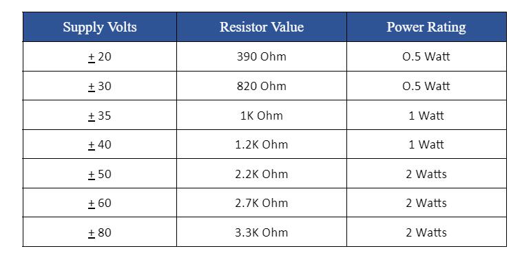
Table 1: R8 Resistor Value For Power Supply Also, here are the resistor values for selecting the power rating and weight of the 3V clipping reference resistor.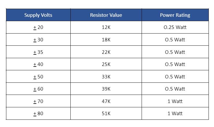
Table 2: R9 Resistor Value for 3volts clipping
And lastly, here's the table for selecting the values and ratings for R10 and R11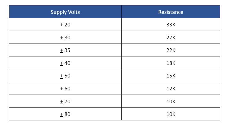 Table 3: R10, R11 Opamp Input Resistors
Clipping Solutions
No doubt, it's straightforward to solve clipping problems. First off, your detector will always let you know when clipping is about to happen. That way, you can avoid it. But you can also add normalization to your audio. By doing so, you can turn up the volume as high as possible without peaking. Primarily, the goal is to ensure your audio source is not peaking and ready to cause clipping mishaps. Also, ensure the sound of your software is at 100% or lower. Hence, It shouldn't go higher than 100%.
Rounding Up
A clipping indicator serves an important role when it comes to audio equipment. Plus, it alerts you when your audio unit is in overdrive and clipping your audio signal. 
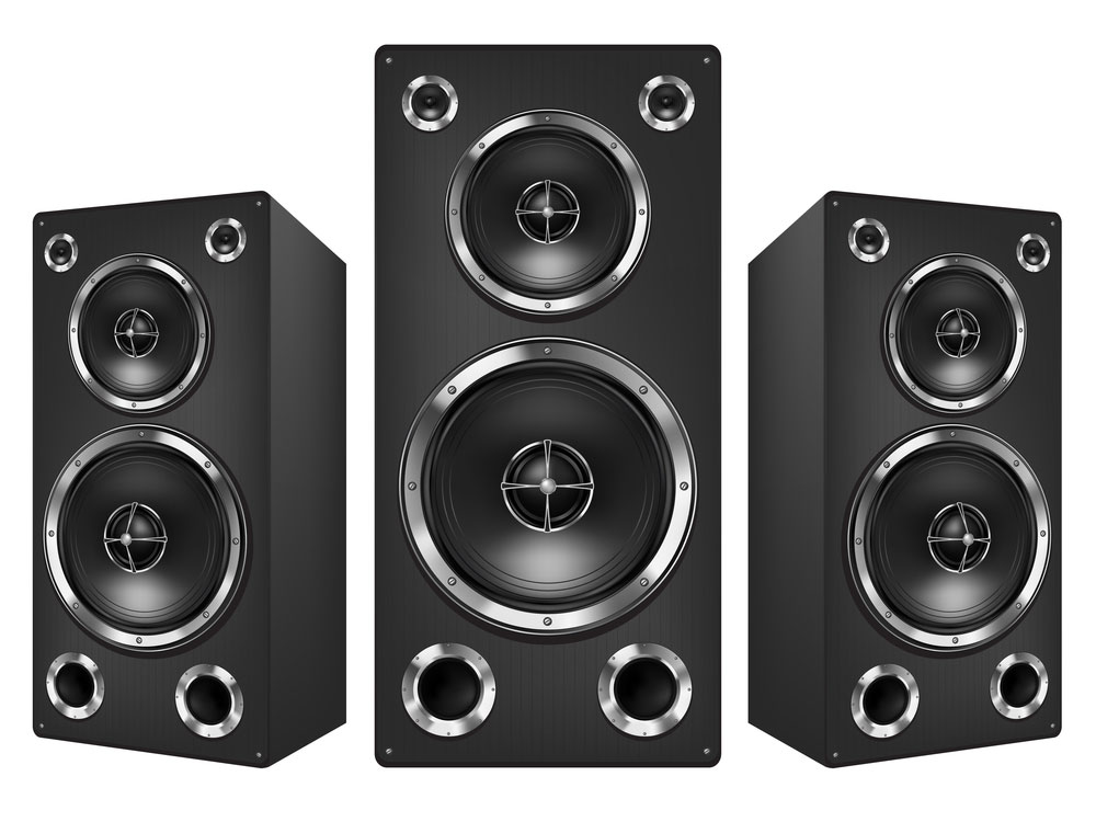
Sound System
Clipping can endanger your equipment and cause irreparable damages if not properly handled. Luckily, you've got info on how to build a simple clipping indicator circuit to save your audio gear from damage. Finally, if you have any questions or suggestions, please get
Comment on this article here
-
No comment

Ripple
Hi everyone, I'm Ripple, Sales Director of KFPCBA Tech Ltd. If you are looking for a one-stop PCB and PCB assembly manufacturer in China, KFPCBA is your best choice! Please feel free to contact our team! Thanks!
Contact me now


