


 tel:+86-18825224069
 email:
 address:201, Factory 6, Longhui Industrial Park, Fuqiao 3rd District, Xinhe Community, Fuhai Street, Baoan District, Shenzhen china
Capacitor on Circuit Board: A Comprehensive Guide
Release date:2022-09-14 11:53:29 Number of views:0
The PCB capacitor on circuit board is one of the essential passive components we employ during the PCB design process. It affects a circuit's performance and quality. During PCB assembly and manufacture, accurate knowledge of the properties and characteristics of capacitors guarantees success in designing your capacitor circuit board.
Additionally, a capacitor in your gadget may damage due to too much heat and voltage. In that case, it requires replacement which you can do by yourself. This article elaborates more about capacitors, from their fundamentals to assembly on the PCB(Printed Circuit Board).
What Is a PCB Capacitor?
A PCB capacitor is an electronic component on a printed circuit board that stores an electrical charge and discharges it into a circuit. It contributes to the smooth operation of an electronic device by controlling the electrical flow throughout the PCB.
PCB Capacitance refers to how much electric energy a capacitor can carry. In its most basic form, a PCB capacitor consists of two conducting plates with a dielectric material.
There are different types of capacitors that have numerous uses. They can swiftly discharge their charge, common in lasers and flashes with capacitive sensing devices.
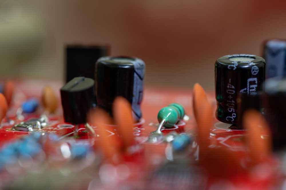
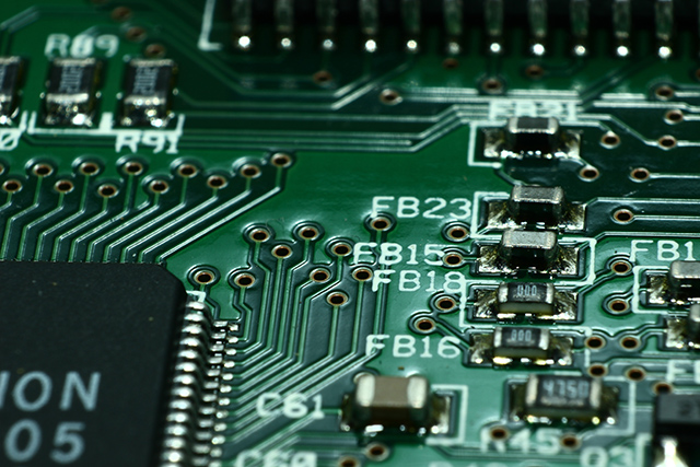
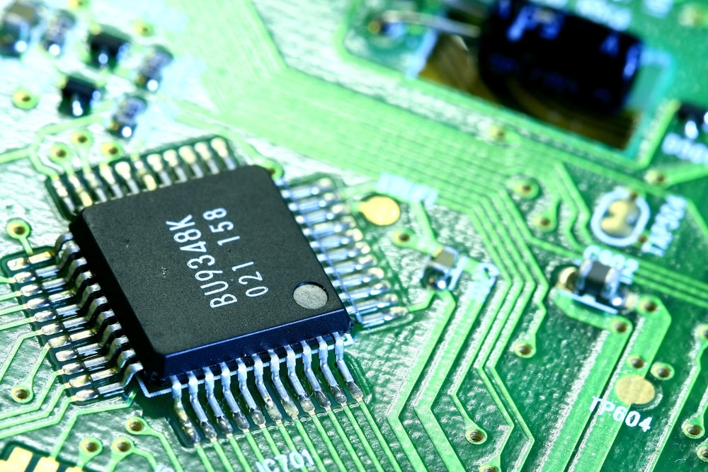
Capacitors on Circuit Board
How Do Capacitors on Circuit Board Work?
Capacitors on a circuit board require a charge to function. The first plate of the PCB capacitor accepts electrical current. The charge builds up on the conductor causing electric charge accumulation on the electrodes.
As more electrons accumulate, the first metal plate becomes negatively charged. Extra electrons then move to the adjacent plate. The result is a positive charge on the second plate.
The electrons on the electrodes do attempt to combine. Nevertheless, the insulator between the two plates stops this from happening. The dielectric is a non-conductive material that impedes the mobility of the charge from traveling between the conductors.
The two metallic plates keep charging as they continue to store electric charge in the capacitor. Eventually, the metal plates will lose their capacity to hold a charge. All of the electrons in the capacitor will discharge if PCB has a conduit for the electrical charge’s movement.
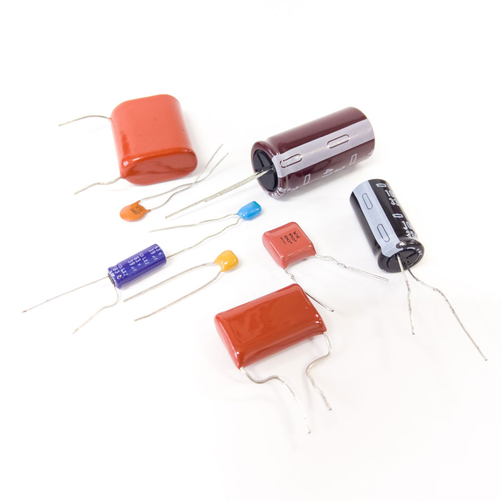
Different types of capacitors
Types of Capacitors
You can categorize capacitors into two — fixed or variable. Fixed capacitors have fixed capacitance values, while variable capacitors have varying capacitance values.
Furthermore, fixed capacitors contain non-polarized and polarized capacitors, while the variable group has tuning and trimming capacitors. Here is a basic summary of the different types of capacitors and their characteristics.
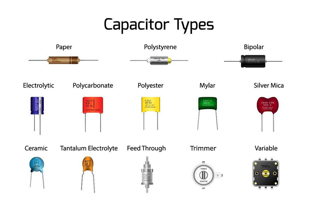
Types of Capacitors
Ceramic Capacitors
Ceramic capacitors have their insulating material made of ceramic material. They have a low capacitance value. Typically, this value lies between 1F to 1µF.
These capacitors leak less current and have a high dielectric constant. Ceramic capacitors are helpful in various applications, including RF and audio.
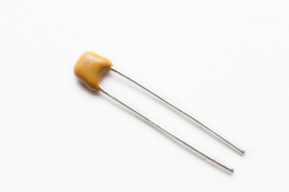
The ceramic capacitor used in electronic (generic capacitor)
Film Capacitors
Film capacitors come in several varieties: polyester, metalized, polypropylene, PTE, and polystyrene.
These capacitors have a high insulation resistance, good temperature characteristics, and no dielectric loss. The film capacitors have low inductance, are stable, and are affordable.
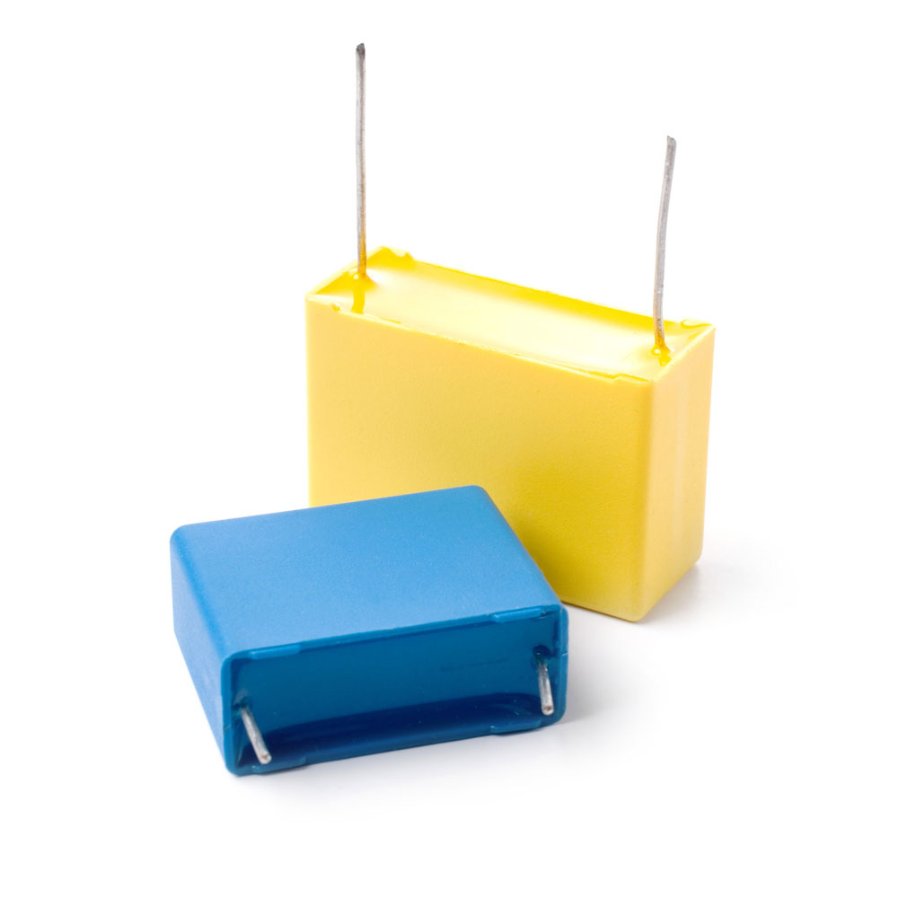 Two film capacitors
Electrolytic Capacitors
Visually, these capacitors resemble small tin cans. Electrolytic capacitors are common in circuits that require larger capacitance. It is because they store a lot of electric currents. The dielectric material is a thin layer of oxide held in small tins.
These are polar capacitors and thus function when wired appropriately; else risk explosion when wired differently.
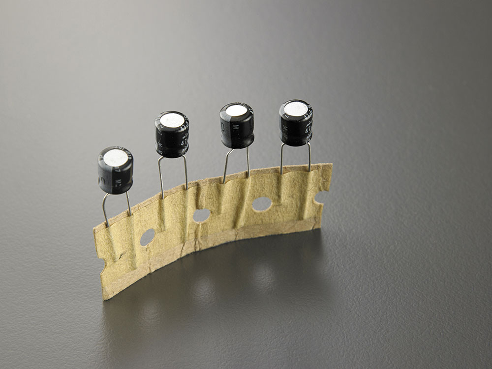
Electrolytic capacitors
Mica Capacitors
The silver mica capacitors consist of metal-coated mica sheets and epoxy-encased to protect the environment. Mica capacitors are essential for a PCB design when compactness, temperature stability, and precision are critical.
They have a low loss of electric charge and are frequently employed at high frequencies. They are also exceptionally stable chemically, electrically, and physically thanks to their unique crystalline structure, typically layered.
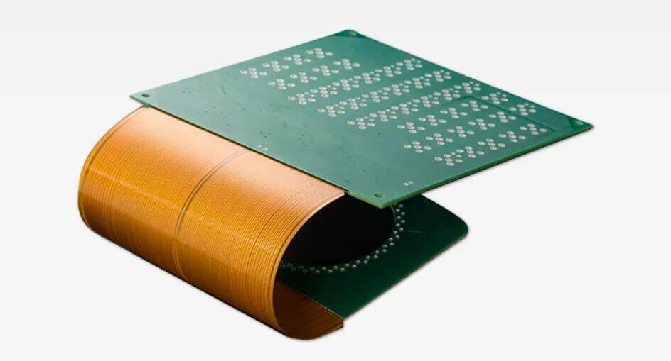
The Role Embedded Capacitors Play in PCB Design
Embedded capacitors have greater capabilities than conventional capacitors. Their small sizes are ideal for use as PCB surface mount capacitors.
During production, thin dielectric material fixes between two layers of copper. The epoxy resin then laminates the copper foils together. It makes the dielectric material in embedded capacitors have a high capacitance density.
Embedded capacitors have automated assembly and low spurious inductance. They function as decoupling capacitors and have incredibly short electrical channels. Besides, these capacitors cut power bus noise and reduce electromagnetic interference (EMI). In this way, parasitic capacitance and inductance are minimal.
Embedded capacitors are useful for telecommunications, computing, medical, and mobile electronic devices. They function as power supply systems filters, which minimize free capacitance.
How To Reduce Parasitic Capacitance in Circuit Board Layout
Parasitic capacitance is prominent between conductors on PCB. It is due to the high-frequency signals passing through the circuit board. The stray capacitance then introduces EMI, which propagates down to adjacent traces.
The following ways come in handy in avoiding stray capacitance;
You can use a faraday shield between traces. A guard ring reduces the capacitive effect between two traces.
You can also increase the space between adjacent traces. You can apply the 2W or 3W rule.
Additionally, use low permittivity dielectric materials since they produce less stray capacitance in the circuit.
Avoid routing the traces in parallel as this leaves a maximum area between the two traces causing maximum capacitance between the traces.
Tips on How To Place Your PCB Bypass Capacitor
One of the essential steps in the design process is the placement of the bypass capacitors. Note that the wrong placement of the bypass capacitors entirely undermines their performance. Here are some tips on how you should place your PCB bypass capacitors.
It would be best if you fixed the PCB bypass capacitors under the pads of top-side SMD components. This aids in creating more room for fanout traces and vias.
When dealing with larger non-polarized capacitors, you should arrange them in ascending value order next to the pin.
For devices with numerous power pins, you need at least one bypass capacitor for each power pin.
Lastly, when installing bypass capacitors, always refer to the schematic because many logic input pins on digital devices are "tied high."
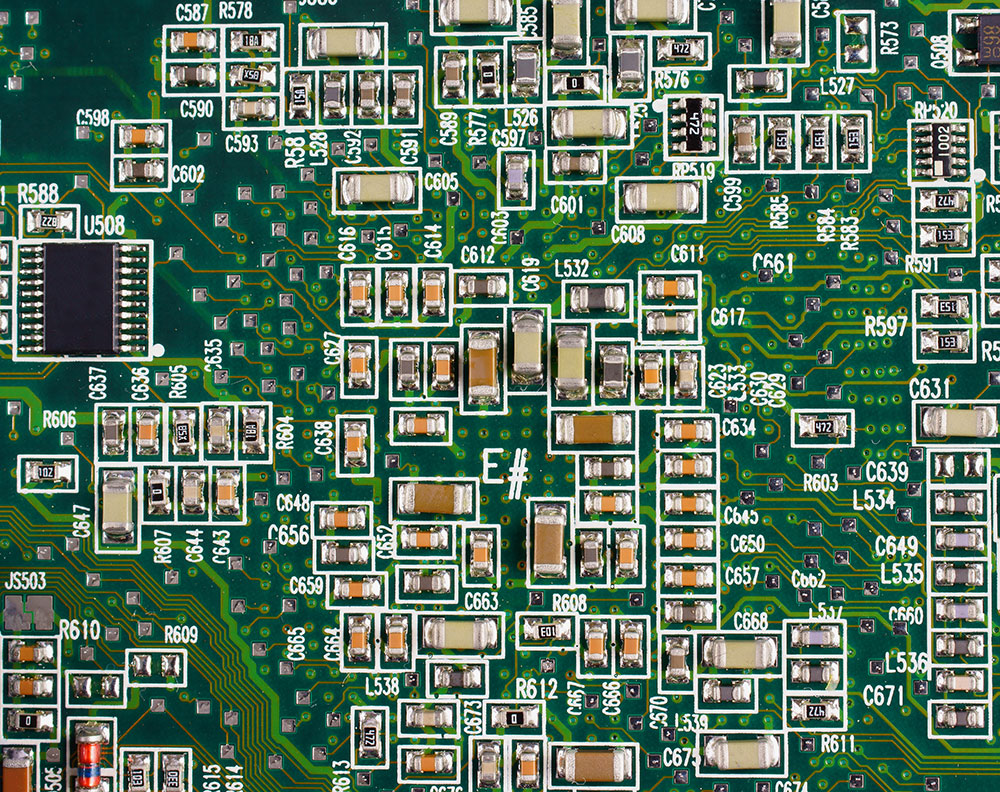
SMD circuit board
Factors To Consider When Choosing Capacitor on Circuit Board
The lifespan of a capacitor: It is the period during which the capacitor will continue to function normally and deliver capacitance as intended.
Voltage stress: Higher (than rated) voltages could harm capacitors. Thus, a capacitor should have a voltage buffer of 50% more than the anticipated voltage drop.
The dielectric type material in the capacitor: A capacitor's dielectric material dictates its capacitance and thermal stability.
Working temperature range of the capacitor: It is generally advisable to consider a buffer temperature of 50% of the maximum ambient temperature.
Tolerance: The tolerance value shows how far a capacitor can deviate from its nominal value in both directions.
How To Replace a Capacitor on Circuit Board
Step 1: When Do You Replace a Capacitor?
A blown-out capacitor may cause system failure due to component failure. Typical signs of a blown capacitor include:
The device won't switch on
It intermittently turns on and off
The screen is flickering or distorted
It is worthwhile to take a few minutes to examine your circuit board capacitors if you are experiencing any of these problems. Most importantly, turn off and unplug your device from the power!
Step 2: Arrange the Tools for Capacitor Replacement
The following tools are essential for capacitor replacement:
Screwdriver
Soldering iron
Replacement capacitors
Soldering wick
Step 3: Access the Damaged Capacitor
Open the electronic casing with your screwdriver to access the circuit board. To open the case, you need to locate numerous screws and tabs.
The top of a blown-out or damaged capacitor will be somewhat curved outwards in a convex form. Check out these signs as they refer to a blown-out capacitor.
Step 4: Remove the Damaged Capacitor
Once you locate the blown-out capacitor, apply a soldering braid to the base of the leads. Push the heated soldering iron against the braid when it is wholly heated to get the solder to heat up and get drawn into the braid.
Remove the capacitor from the circuit board by pulling until the leads of the capacitor are free of solder. The Remove residual solder from the circuit board's contact points using a soldering wick.
Remove a damaged capacitor on a circuit board.
Step 5: Install the New Capacitor
Installing the new capacitor requires trimming the new capacitor's leads to make them even and sit at a similar height to the previous capacitor. Then place the leads of the new capacitor in the holes where the old capacitor formerly stood.
Consequently, place the soldering iron's tip directly onto the joint on the circuit board's back. Press the wire lead through the hole as soon as the tip of the iron touches the hole, then take it out. The old solder joint will harden and secure the new portion inside of it.
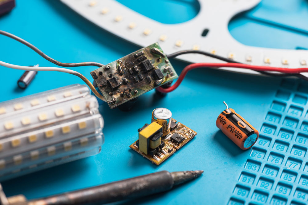
Disposing of Your PCB Capacitor
Crushing and shredding are no longer acceptable substitutes for disposing of PCB capacitors. Leaky PCB capacitors are harmful to the environment.
Therefore, disposing of your PCB circuit boards requires direct disposal at a TSCA- or Hazardous Waste-approved disposal facility. A transporter permitted to haul PCB waste will pick them up for proper disposal.
PCB board and electronic components
Summary
Although people overlook passive components in electronic circuit boards, they are essential for PCB assembly and manufacture. Particularly for semiconductors that run on direct current, capacitors are essential companions.
In case you have any questions, please contact us on our website.
Comment on this article here
-
No comment

Ripple
Hi everyone, I'm Ripple, Sales Director of KFPCBA Tech Ltd. If you are looking for a one-stop PCB and PCB assembly manufacturer in China, KFPCBA is your best choice! Please feel free to contact our team! Thanks!
Contact me now
Relevant content you may be interested in
Related articles


