


 tel:+86-18825224069
 email:
 address:201, Factory 6, Longhui Industrial Park, Fuqiao 3rd District, Xinhe Community, Fuhai Street, Baoan District, Shenzhen china
Temperature Controller Circuit board: What Makes it Tick?
Release date:2022-05-31 15:26:08 Number of views:0
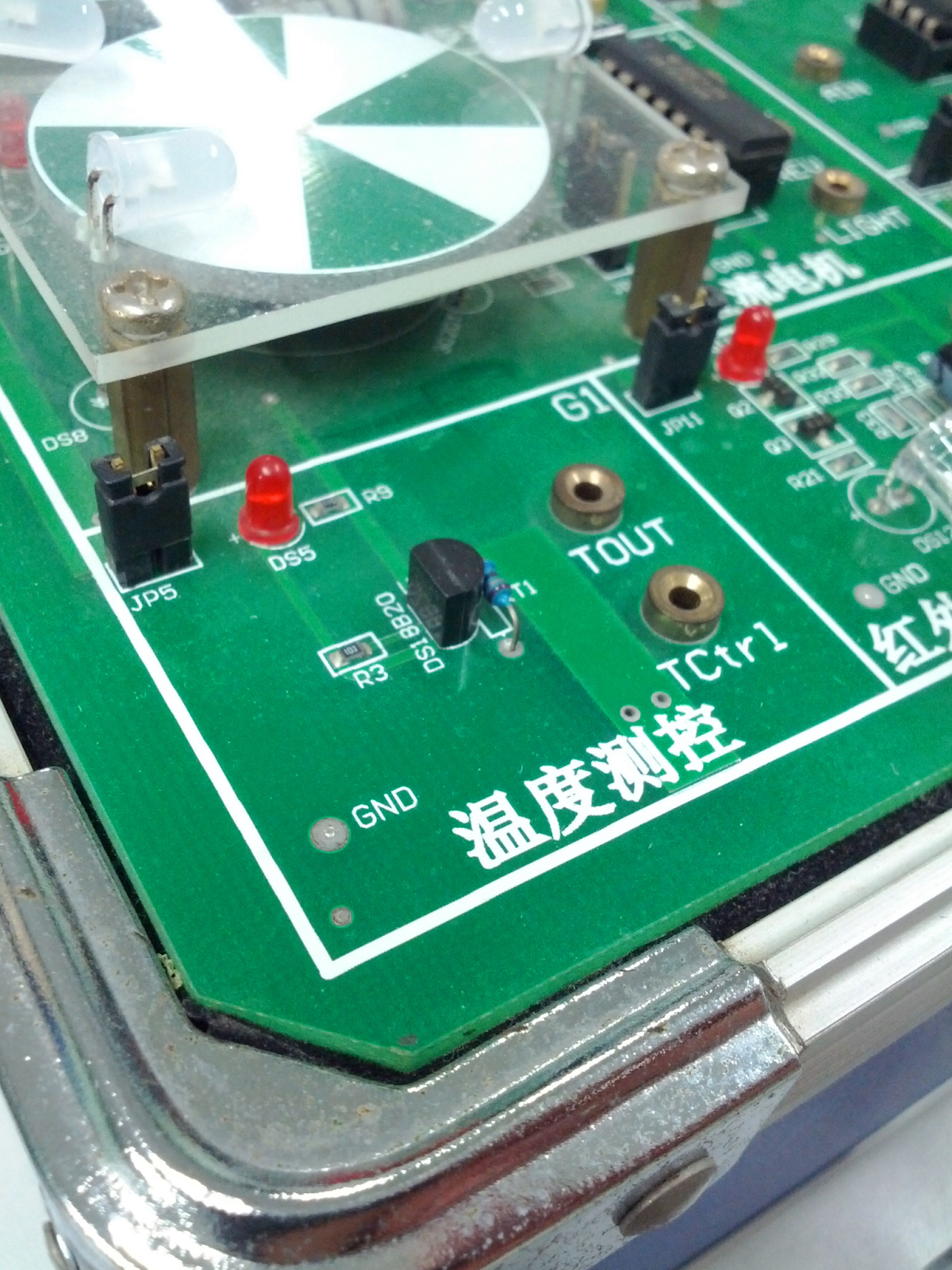
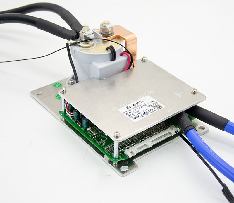
Temperature Control Circuit
Source: Wikimedia Commons
Control applications offer a lot of project ideas. But, in truth, you can control various devices and appliances with the right circuit. So, perhaps, the question you need answers to is: What can I do with a temperature controller circuit?
A temperature controller can do many things beyond turning a thermostat on and off.
Luckily, this article will guide you on building a temperature control circuit and what you can do with it.
Let’s get started!
What is a Temperature Control Device?
As the name implies, temperature control devices can control heaters or other devices based on the temperature while handling cold or heat exposure.
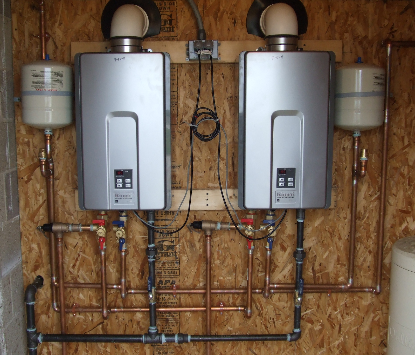
Heater
Source: Wikimedia Commons
You can set a temperature threshold and configure a temperature controller to turn off or on any device you attach to it.
Also, these devices offer precise and accurate temperature control while working in various industrial, home, and even medical applications.
For instance, a temperature control device will be perfect for temperature-sensitive devices, like incubators.
How Does a Temperature Controller Switch Work?
A temperature control switch works according to a set value (temperature threshold). Interestingly, it does this by measuring the room’s environmental conditions or device and comparing it to the temperature threshold.
Then, the temperature controller uses the difference between the two values to determine the action to take. In the end, it would decide if the device needs heating or cooling.
When the device finishes its calculations, it sends out an output power signal. This output signal carries out the necessary changes. Also, the final control element (heater, fan, or other devices) is what receives the signal and cools or heats the attached device.
Imagine an oven with a heater, thermocouple, and a controller to understand better how it works. The controller measures the oven’s thermocouple’s temperature and compares it to the set threshold.
Oven
Source: Wikimedia Commons
Also, the controller calculates how long the heater would keep running to maintain the oven’s environmental conditions.
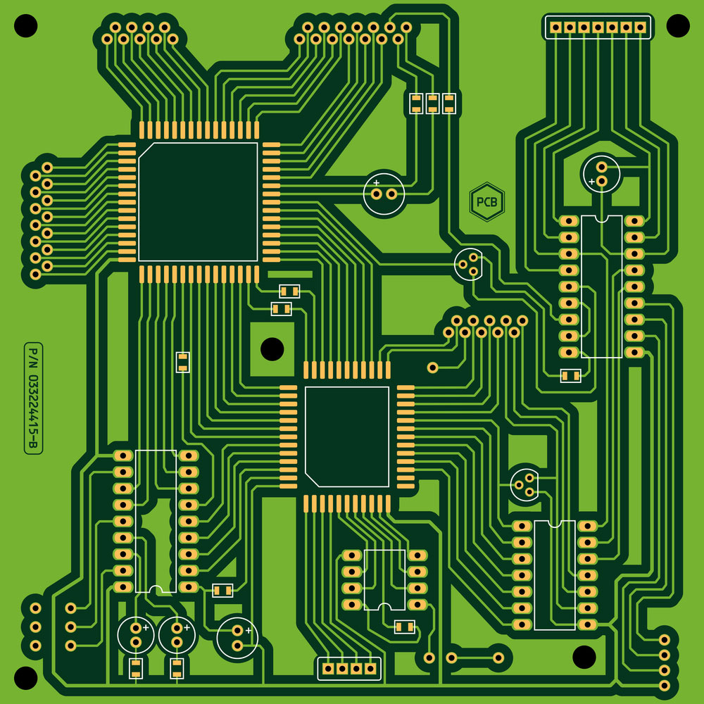
Temperature Control Circuit
You can build various temperature control circuit systems like:
Temperature-controlled relay circuit
555 temperature controller circuit
Temperature-controlled relay with Arduino
Temperature-controlled DC fan
Now let’s go into how to make these circuits and how they work.
Temperature Controlled Relay Circuit
First, we have this temperature control circuit that’s easy to workaround. It’s one of the easiest temperature circuits to create, but that doesn’t make it a less effective system. In short, it’s pretty practical for automatic temperature control applications.
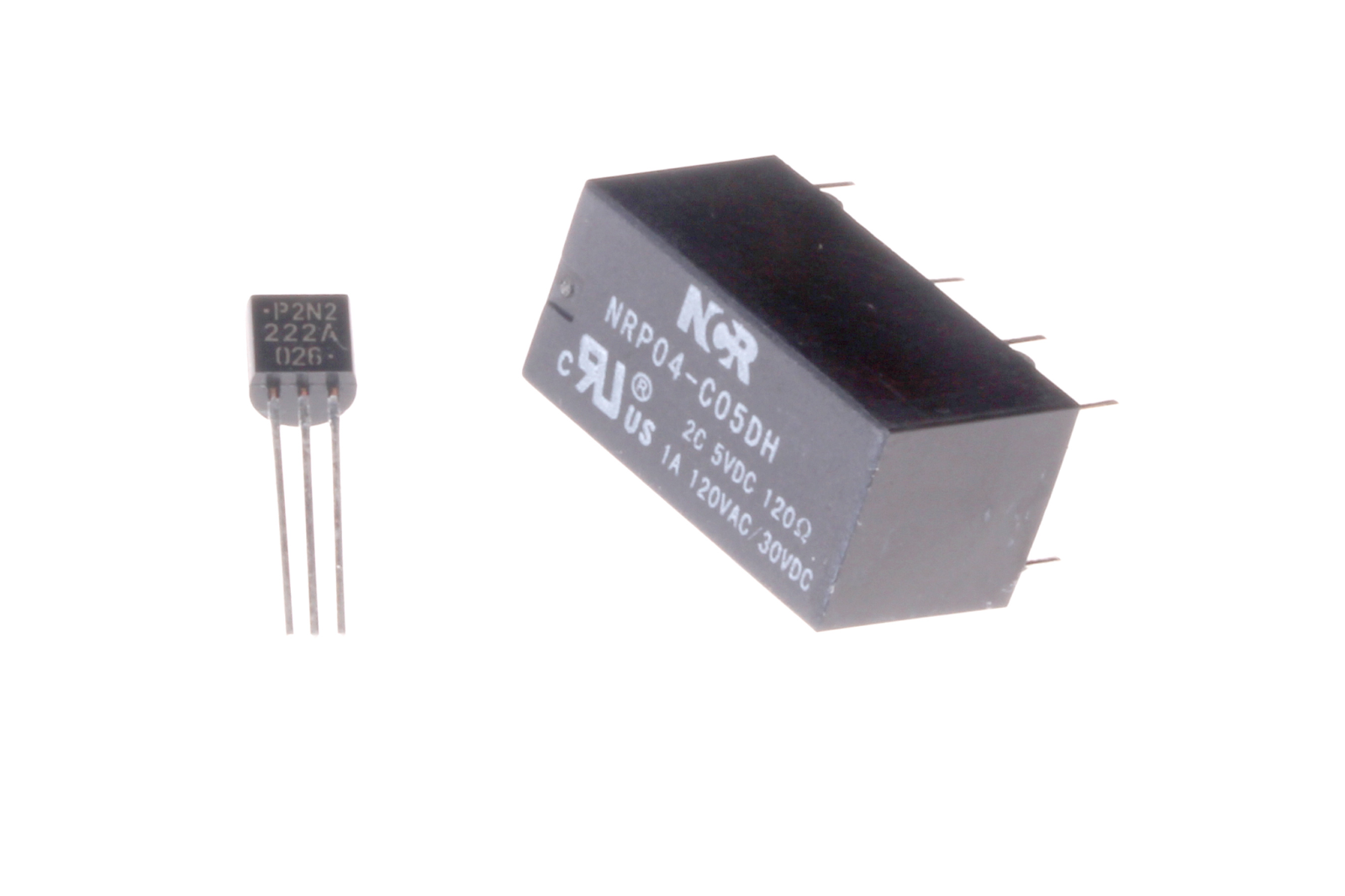
Miniature Relay
Source: Wikimedia Commons
This temperature controller controls a relay connected to the circuit. It utilizes an LM35DZ single-chip temperature sensor for this task.
When the temperature crosses the temperature settings, the relay starts operating. But, if the temperature goes below the point, the relay stops working.
Components Needed
LM35DZ (IC1)
TL431 (IC2)
LM358 (1C3)
D1-2: 1N4148 Diode (2)
D3-4: 1N400X Diode (2)
Zener diode (13v, 400mW)
PNP transistor (Q1)
Trim pot preset: 2.2k Temperature threshold
Resistors 1-6 (10k, 4.7M, 1.2K, 1K, 1K, and 33Ω)
C1- Ceramic or mylar capacitor (0.1 uF)
C2- Electrolytic capacitor (470 uF or 680 uF)
Small relay
How it Works
The LM35DZ temperature sensor is the central unit of this circuit. It works with the Celsius scale and uses a degree to volt conversion to provide accurate control.
Also, the LM35DZ changes its output power voltage according to the temperature measured. Plus, the maximum temperature can be anywhere between zero degrees (0V) to 100 degrees celsius (1000mV).
The R3 (resistor) and VR1 (preset) of this circuit are responsible for the temperature settings of the circuit from 0V to 1.62V. Additionally, the op-amp lessens the reference voltage to prevent overloading the VR1 and R3.
Then, the comparator kicks in and compares the LM35DZ’s output voltage with the temperature settings. It also decides if the relay needs to be turned on or off.
Temperature Controlled Relay with Arduino
This temperature control circuit does a great job in controlling DC fan relays. The fun part is that the circuit uses an Arduino board, not limited to a DC fan. So you can switch the DC fan to a light bulb or other electrical devices.
This circuit automatically turns on the fan or device when it reaches the maximum temperature limit and switches it off when it goes below.
Here’s what you need for this project:
Temperature sensor (LM35)
Arduino UNO
16 x 2 LCD (1)
9v Battery (1)
Relay module (1)
Jumper wires
9v/12v DC fan
Here are the necessary steps to take.
Step One: Make Your Connections
Use the schematics below to connect all your hardware:
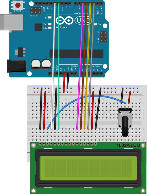
Arduino and LCD connections
Source: Wikimedia Commons
Relay Connections
DC Fan Connection
Step Two: Software Time
After setting up your hardware, here’s the Arduino sketch for the software part:
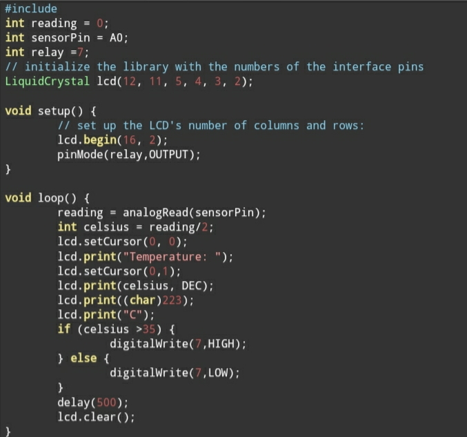
Arduino Sketch
Source: Screenshot from Arduino
Now you’ve got one digital temperature sensor made with Arduino. But, if your fan still doesn’t work, check the GND connections of the Arduino and battery.
Also, if you get nothing on your LCD after uploading your code, modify the potentiometer of the LCD. Then, continue making adjustments until the LCD responds.
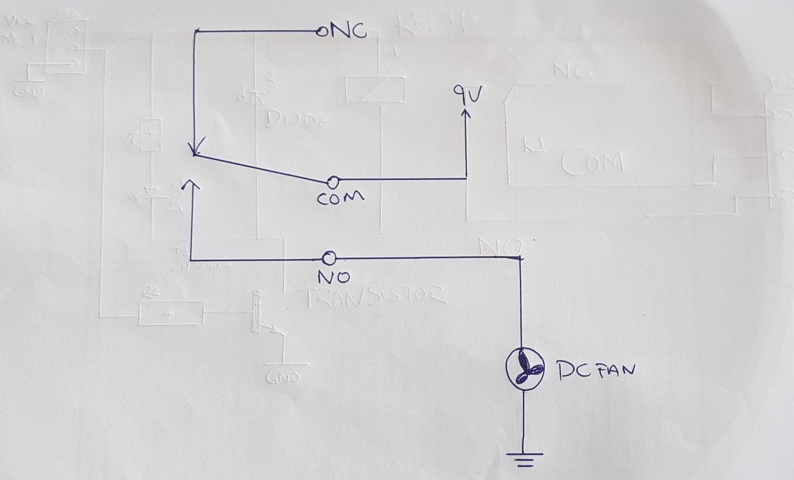
Temperature Controlled DC Fan
Contrary to the Arduino project that only switches on a device, this circuit controls a DC fan to maintain the temperature of any device attached to it.
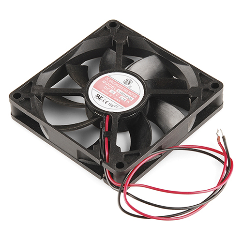
DC Brushless Fan
Source: Wikimedia Commons
Like the other projects, this circuit turns on the fan when the core temperature exceeds its presets and turns it off when it gets lower. It’s also fully automatic.
Here’s what you need for this project:
Thermistor (4.7k NTC)
Voltage comparator (IC uA 741)
12V Brushless DC fan (1)
VR (500K)
1N4007
T1 (BD140)
R1 (4.7K)
R2 (47 Ω)
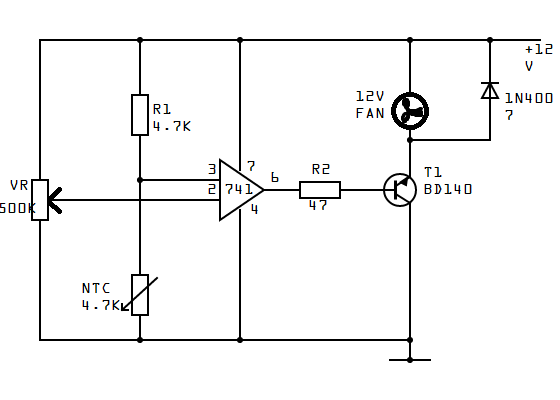
How it Works
The circuit uses an NTC (Negative Temperature Coefficient) thermistor that drops the resistance as the temperature rises. When the circuit normalizes, the fan goes off. But when it gets hotter and beyond the maximum temperature point, it activates T1 on the circuit.
At this point, the DC fan will turn on to cool down the rising temperature. When everything goes back to normal, the fan will switch off automatically. Also, you can use electrical power or batteries to power this circuit.
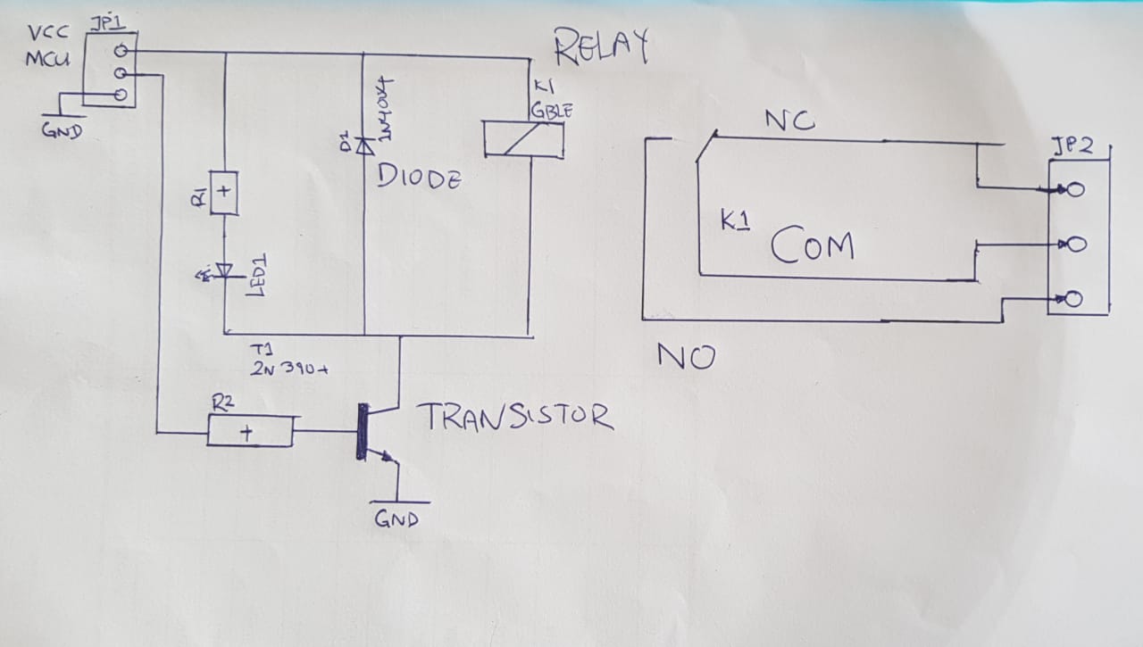
Here are the schematics below to help build this circuit:
Circuit Schematics
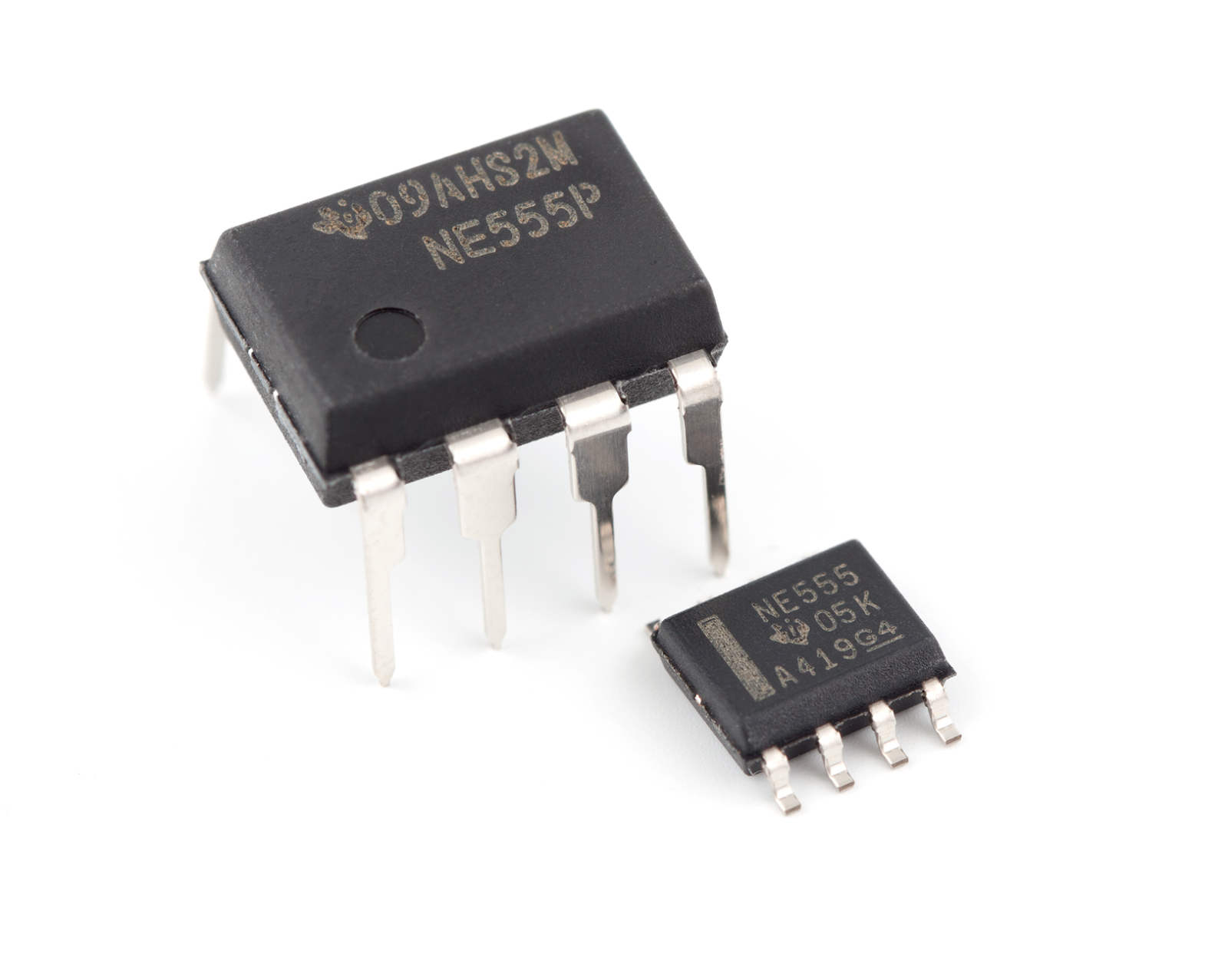
555 Temperature Controller Circuit
Working together with the 555 IC is a thermistor resistor divider.
555 IC
Source: Wikimedia Commons
With this circuit, you won’t need to regulate any power supply. The dividing network of the circuit is capable of handling that task. Plus, the network includes an adjustable resistor (R3) and thermistors (R4 and R5)
How it Works
Like the previous project, something happens when the temperature increases or decreases. In this case, a temperature decrease activates a controlled heater and a timing cycle.
If the core temperature crosses the threshold before the timing cycle ends, the circuit will turn off the heater. However, the heater will remain active if it doesn’t reach the maximum temperature due to cold exposure.
You can get the components needed and build this circuit by following the schematics below:
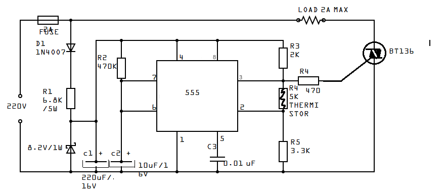
Circuit Schematics
Last Words
A temperature control circuit is a great way to control temperature-sensitive applications automatically without leaving your comfort. You can even avoid the several effects of temperature.
In truth, the circuit is easy to build, doesn’t require any expensive parts, and is similar to a heat sensor.
So, what do you think about building a temperature control circuit? If you need any help, don’t hesitate to contact us.
Comment on this article here
-
No comment

Ripple
Hi everyone, I'm Ripple, Sales Director of KFPCBA Tech Ltd. If you are looking for a one-stop PCB and PCB assembly manufacturer in China, KFPCBA is your best choice! Please feel free to contact our team! Thanks!
Contact me now
Relevant content you may be interested in
Related articles


