


 tel:+86-18825224069
 email:
 address:201, Factory 6, Longhui Industrial Park, Fuqiao 3rd District, Xinhe Community, Fuhai Street, Baoan District, Shenzhen china
Metal oxide varistor (MOV) is a voltage surge protection device
Release date:2022-02-22 15:48:54 Number of views:0
Circuits and electronics are a significant part of our lives and day-to-day activities. Unfortunately, voltage spikes can occur for several reasons and cause damages to electronic systems. However, you can use metal oxide varistors to safeguard the circuit. These varistors are not new because they date back to the early 70s and have become the preferred method for protecting circuits.
MOVs are ideal for various applications, especially on circuit boards. Here's all you need to know about this electronic component.
What Are Metal Oxide Varistors?
In simple terms, a metal oxide varistor is a variable resistor but with a slight twist. Unlike a potentiometer, it can change the resistance based on the input voltage. An increase in voltage reduces the resistance while a voltage decrease raises the resistance.
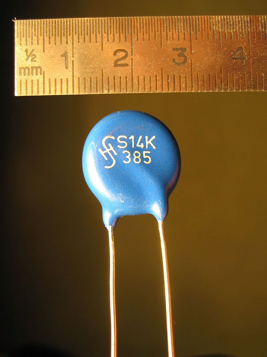
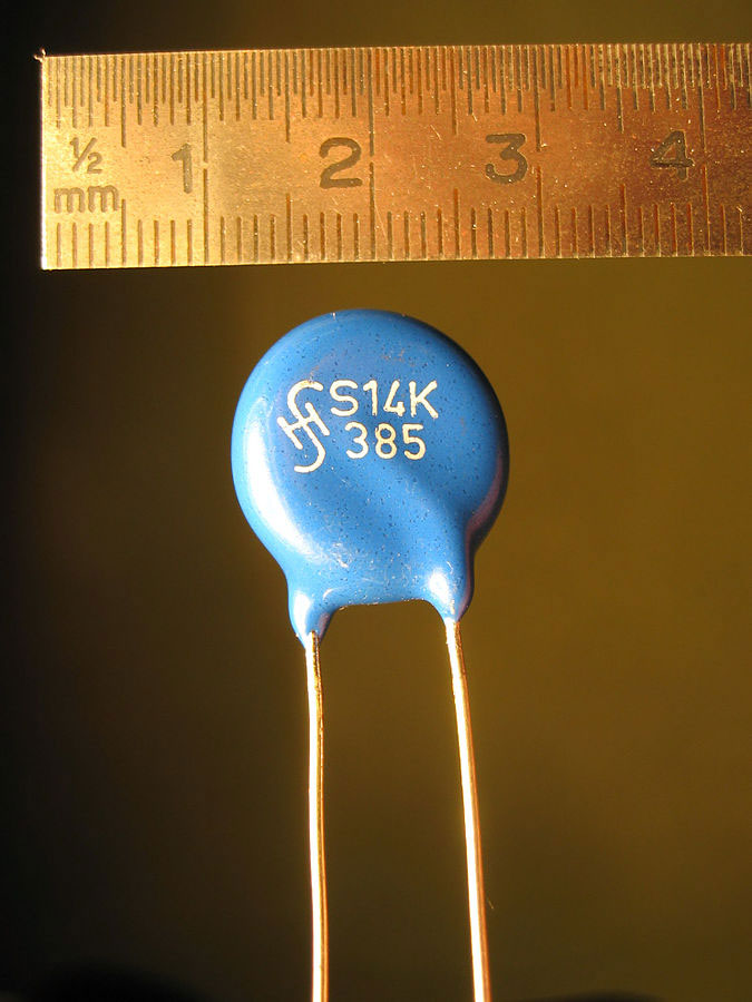
A Metal Oxide Varistor
Source: Wikimedia Commons
With this electrical property, the varistor comes in handy in circuit protection technologies.
How Does MOV Work?
Metal Oxide Varistors come in a wide range of voltage variations, ranging from about 10V to more than 1,000 volts AC or DC. Therefore, selecting or constructing one is easier if you know the supply voltage.
For instance, if the voltage supply is 120V, pick a silicon or metal oxide varistor with a slightly higher RMS voltage, like 130V. If the power is 230V, pick a varistor with an RMS value of 260V.
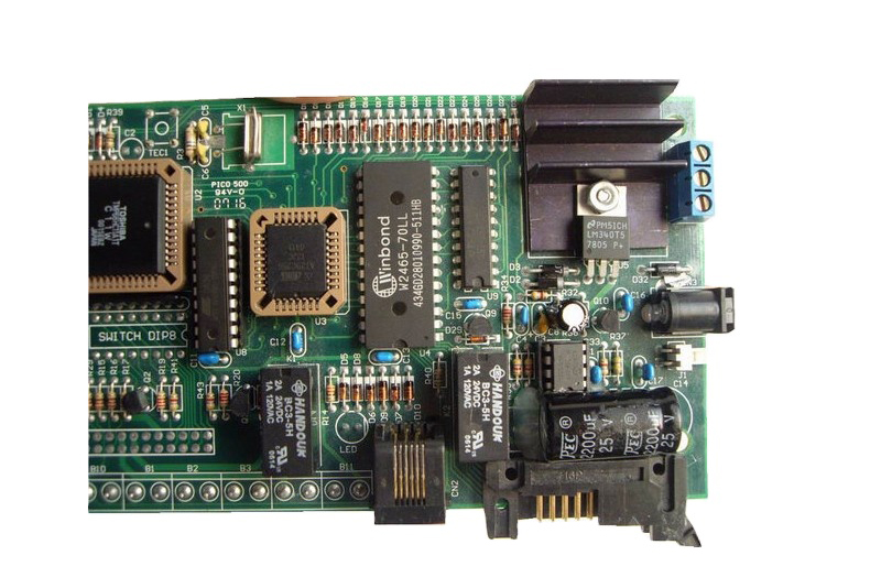
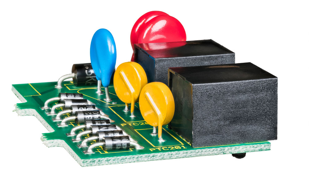
A metal oxide varistor on a circuit board
Source: Wikimedia Commons
Apart from the supply voltage, it is also essential to understand the transient power pulse and source impedance. It is challenging to pick the correct MOV for incoming lines and phase-borne transients because the power supply characteristics are unknown. Therefore MOV selection for electrical circuit protection from spikes and supply transients is usually an educated guess.
However, when dealing with current, the maximum surge that the varistor can take depends on the number of pulse repetitions and transient pulse width.
You can make assumptions on the transient pulse width, which usually measures 20 - 50 microseconds long.
That said, the varistor might overheat if the peak pulse current rating is insufficient. Therefore, it must dissipate the absorbed transient pulse energy quickly and return to its pre-pulse condition to prevent catastrophic failure.
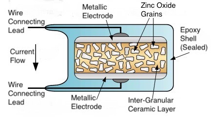
MOV Construction
Metal oxide varistors contain one main component: a ceramic powder of metal oxide. The most commonly used varistor material is Zinc Oxide (ZnO grains), but oxides of cobalt, bismuth, and manganese can also work.
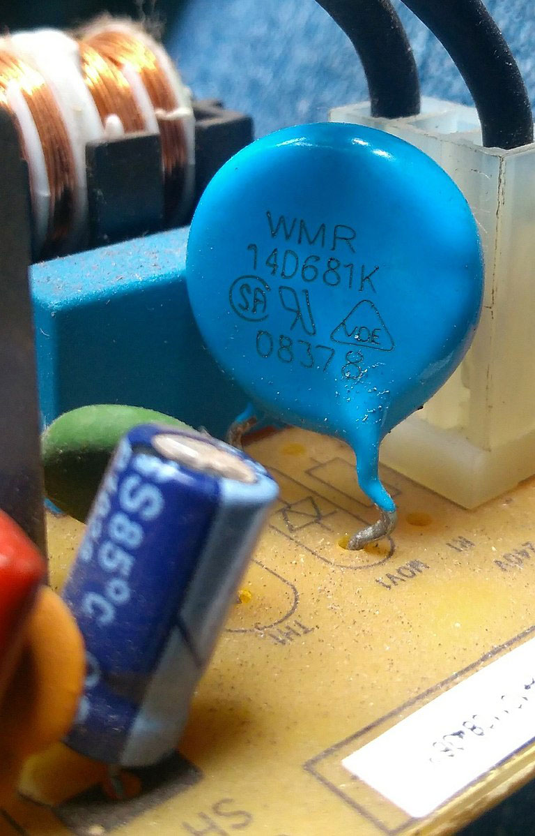
A Metal Oxide Varistor construction
Source: Wikimedia Commons
Two metal electrodes hold the ZnO grains in place, and each grain creates a diode junction with the adjacent one. Thus, an MOV is like back-to-back diode pairs connected in series.
A small voltage across the electrodes results in reverse leakage current, but a large voltage weakens and breaks down the diode borders junctions. This issue results from avalanche breakdown and electron tunneling.
That said, the varistor only starts conducting when the voltage at the connecting leads exceeds the threshold voltage. Therefore, you should connect them in series if you want a high voltage rating. But if you prefer a more effective energy handling capability, join them in parallel.
Electrical Characteristics of MOV
To understand the properties of a MOV, you need to know its electrical characteristics, which include the following:
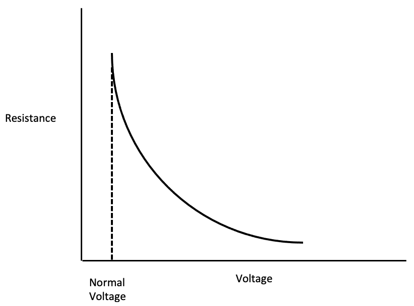
Static Resistance
When you plot a graph of the MOV's voltage against resistance, the resistance is at its peak at the standard voltage. However, as the voltage rises, the resistance decreases.
A static resistance curve
This graph is important because it helps you understand the amount of resistance in the MOV across different voltages.
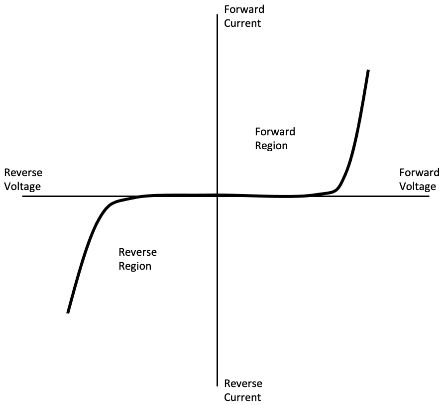
V-I Characteristics
Following ohm's law, the V-I characteristic of a linear resistor is a straight line. But with a varistor, it forms two symmetrical bi-directional curves. The curve resembles the attributes of two back-to-back Zener diodes.
When not conducting, the varistor device has a high resistance and maintains this resistance up to about 200V. However, if the voltage range is 200-250V, the resistance decreases, allowing current to flow through the device. This small current flow forms the slight curves on the graph.
However, once the voltage exceeds 250V (rated/clamping voltage), the varistor device delivers better electrical conduction, allowing about 1mA to flow through.
The MOV's resistance reduces significantly if the transient voltage spikes to equal or exceed the clamping voltage. At this point, the avalanche effect of the semiconductor material effectively turns the varistor into a conductor.
Capacitance of MOV
Since the MOV has two electrodes, it acts as a dielectric medium and produces the effect of a capacitor. The capacitance value depends on the area, which inversely relies on the thickness.
That said, the allowable varistor capacitance is not an issue in DC circuits because it remains constant until the device's operating DC voltage range equals the clamping voltage.
However, with AC circuits, capacitance might affect the overall body resistance, resulting in leakage current. Since the MOV connects to the device under protection parallel, the resistance lowers as the frequency rises. Such a scenario increases the leakage current, creating a non-conducting leakage region in the V-I curve.
You can calculate the MOV's reactance value using this formula:
Xc = 1/2πfC
Xc is the capacitive resistance, and f is the AC frequency,
MOV Performance
Fuses and circuit breakers are also protection devices, but their working mechanisms are similar to MOVs. Varistors are non-linear and voltage-dependent, where their resistance changes automatically based on the power supply.
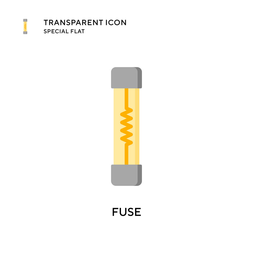
A fuse
Varistors provide almost complete protection from catastrophic failures, with devices like the Littelfuse varistor delivering the broadest range of circuit protection. However, the device can experience permanent damage if the voltage it is suppressing is too high.
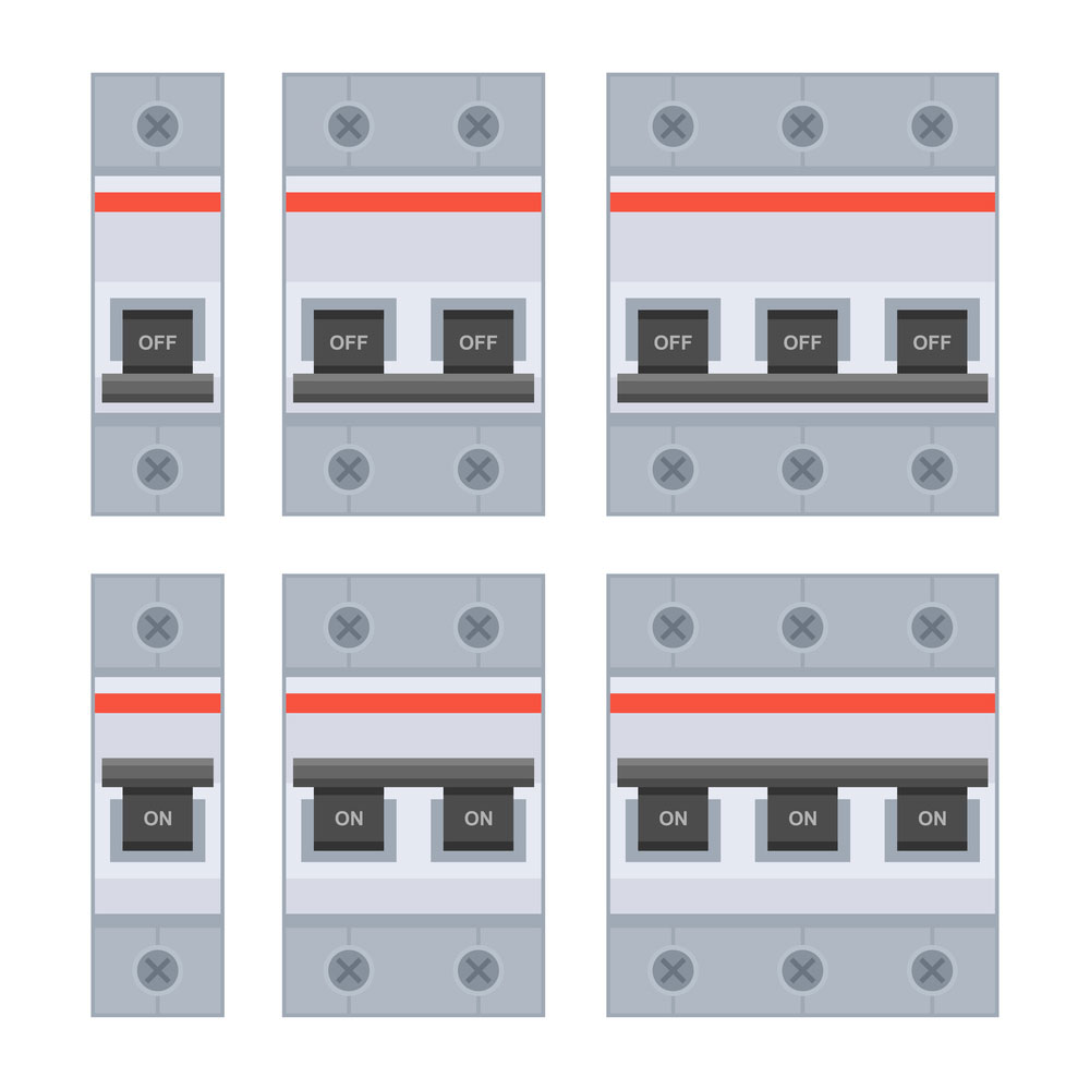
Circuit breakers
Since even small spikes cause minor damages, the device becomes slower over time, and manufacturers usually explain the life of the device via a chart.
The energy rating also affects the varistor's lifespan. A high energy rating changes the transient pulses that the device can handle, which raises the clamping voltage on every brief breakdown.
You can improve the performance by linking multiple MOVs in parallel. Also, you can interfere with the response time by altering the component lead inductance and mounting design.
It is worth noting that a metal oxide varistor can function in both forward and reverse bias.
MOV Specifications
Before picking a metal oxide varistor, you need to know its parameters, which include the following:
Maximum Varistor Working Voltage
Also referred to as the steady-state DC voltage, this voltage is where the leakage current is lower than the specified value.
Clamping Voltage
Refers to the voltage at which the varistor begins conducting while dissipating the surge current.
Surge Current
Surge current is the peak current that the device can handle without experiencing any damages, and manufacturers usually express it as current for a given time.
Varistor
Surge Shift
The voltage variation after a transient voltage spike is the surge shift.
Energy Absorption
Refers to the maximum amount of energy that the varistor can dissipate for a specified period. The standard transient x/y expresses this energy, with x being the transient rise while y is the time to reach the half peak value. You can determine this value by powering the devices in a controlled circuit with specific values.
Response Time
After a spike, the period a MOV takes to begin conducting is the response time (usually at 100nS).
Maximum AC Voltage
Also referred to as the maximum RMS line voltage, this value is usually above the actual RMS line voltage. The peak and varistor voltage should not overlap because they might reduce the lifespan of the electronic components.
Leakage Current
Lastly, leakage current flows through the varistor when operating below clamping voltage and with no surge in the circuit.
How To Use A MOV In Your Circuit?
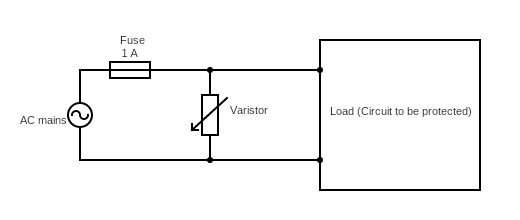
In most cases, a MOV sits alongside a fuse in parallel in the circuit, as shown below:
A MOV connected in parallel.
When there is no voltage spike, the resistance in the MOV device will be very high, so no current will flow through it. Instead, all of it flows into the circuit.
However, a spike exceeding the AC voltage range occurs immediately across the MOV because it is parallel to the power supply. Such surges lower the electrical resistance value in the MOV, allowing current through.
Since the resistance lowers drastically, the current flow through the MOV goes very high, appearing like a short. This flow blows the linked fuse and cuts off the power supply to the circuit.
However, voltage spikes don't usually last long enough to blow a fuse, so the circuit resumes regular operation without requiring a fuse replacement.
But each voltage spike leaves a mark on the varistor, so catastrophic MOV failure means it must have undergone multiple surges.
MOV Protection Circuit Design Tips
When designing the PCB, use the following tips.
Determine the continuous working voltage that will run across the varistor. Remember to pick the MOV with the max AC/DC voltage that matches or exceeds the applied voltage. Ideally, it should be 10-15% more than the line voltage. However, if you want to minimize leakages as much as possible, use a varistor with a high operating voltage.
Determine the energy absorption of the MOV device in the surge event. Pick a varistor that dissipates more energy, equivalent or slightly more than the required energy dissipation performance in the circuit during a surge.
Also, determine the surge current through the varistor. It is better to pick a varistor with a surge current rating that either equals or exceeds the required current rating for any spike that might occur in the circuit.
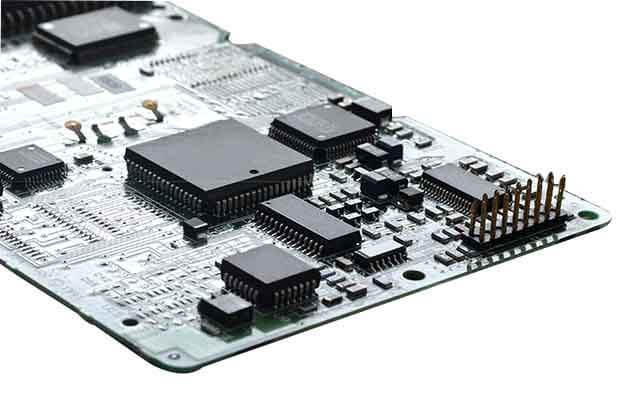
A MOV on a circuit board
Similarly, determine the required power dissipation required in the circuit, then pick a MOV with an equal or higher power rating.
When dealing with the energy, surge, and current rating, it is best to pick varistors with the highest ratings possible. If not, make sure they exceed what you anticipate in the circuit.
Lastly, select a MOV that can deliver the required clamping voltage. You can determine this value based on the max voltage value allowed for the input/output during a spike.
Applications of MOV
Applications for varistors include the following:
Protection from overvoltage, voltage-spike, Line-to-Line, arching, and switching
Protects devices from faults
Prevents switching device failures, such as transistors, MOSFETs, and thyristor bridges
A power MOSFET
Source: Wikimedia Commons
Surge protection to regular electronic devices, like mp3 players, digital cameras, etc.
Safeguard industrial power systems, data systems, AC & DC lines, etc.
Used in adapters and strips
Summary
In conclusion, MOVs have unique electrical properties, making them critical for electronic devices. It is a simple component with few varistor materials but is very handy in protecting against AC voltage surges. If you have any questions about this device, contact us for us.
Comment on this article here
-
No comment

Ripple
Hi everyone, I'm Ripple, Sales Director of KFPCBA Tech Ltd. If you are looking for a one-stop PCB and PCB assembly manufacturer in China, KFPCBA is your best choice! Please feel free to contact our team! Thanks!
Contact me now


