


 tel:+86-18825224069
 email:
 address:201, Factory 6, Longhui Industrial Park, Fuqiao 3rd District, Xinhe Community, Fuhai Street, Baoan District, Shenzhen china
Radar PCBA: RF Circuit Boards for Inspection and Automation
Release date:2022-02-17 10:43:12 Number of views:0
Technological advances have pushed us to create systems that interact with the environment then make decisions appropriately. Such a level of automation requires powerful hardware specifically suited to send and receive signals from the surrounding environment. Radar PCBA are critical hardware for this job because they assist in detecting objects or spotting targets. There's much more to learn about these circuits, so let's get right into it.
What is Radar PCB?
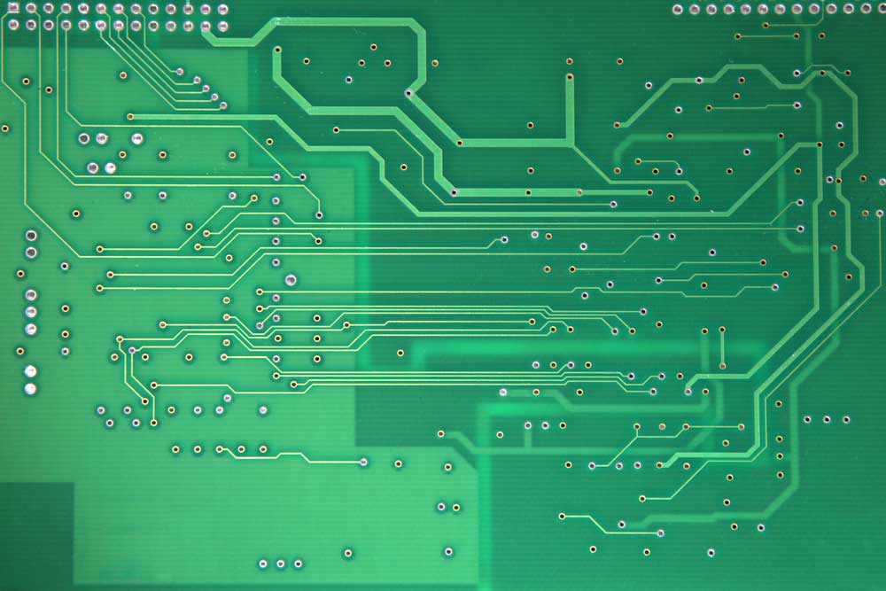
A radar PCB is an electrical circuit responsible for producing, transmitting, and receiving radio frequency signals.
To clarify, it contains an antenna structure mounted on a high-frequency laminate material that transmits a radar lobe generated by the RF circuit.
Also, the same antenna receives the reflected radar pulse after hitting an object, and the RF circuit analyzes it.
A radar horn PCB
Source: Wikimedia Commons
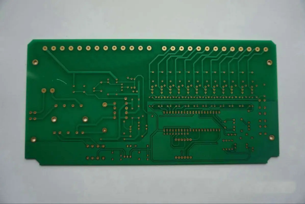
Usually, the modern radar PCB features a digital circuit at the rear for analyzing the echo while the RF and antenna sections sit at the front.
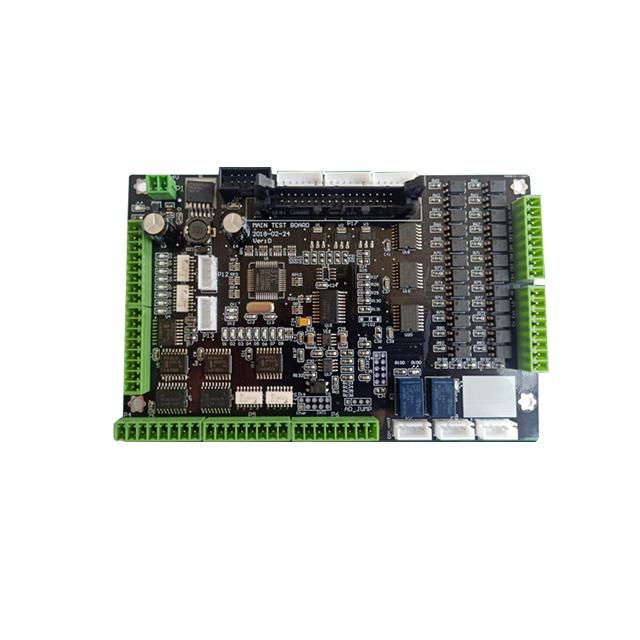
The Fundamental Parts Of A Radar PCB
The essential parts of a radar PCB include:
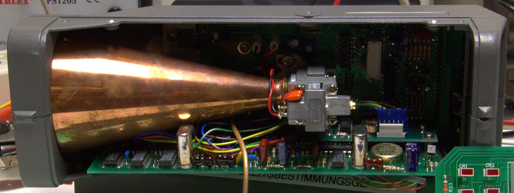
Transmitter: A signal from the waveform generator is not strong enough for radar. Therefore, the purpose of a transmitter is to amplify the signal using a power amplifier.
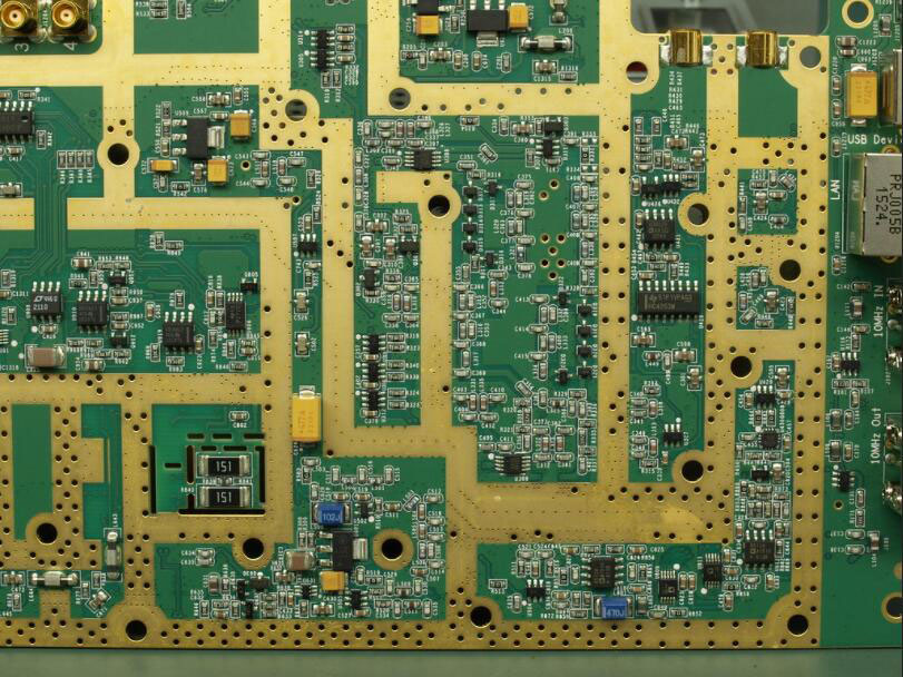
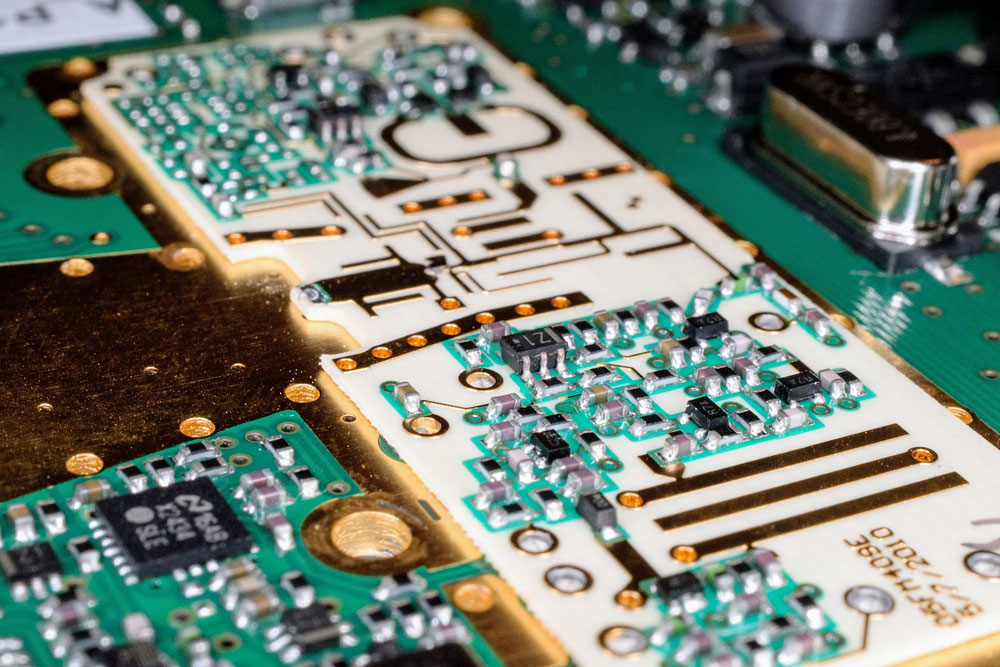
An RF signal generator circuit
Source: Flickr
Receiver: A receiver detects and processes the reflected signal using a receiver processor, like the super-heterodyne.
Antenna: Contains parabolic reflectors, planar arrays, or electronically steered phased arrays. It is responsible for sending out and receiving the pulses.
Duplexer: A duplexer is a device that enables the antenna to do the tasks of a transmitter and receiver.
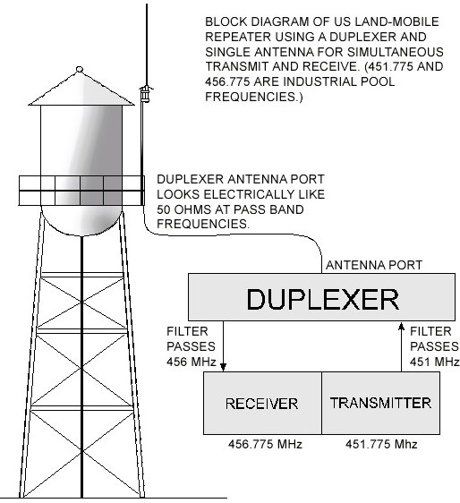
How a duplexer works
Source: Wikimedia Commons
Waveguides: Waveguides are the transmission lines for transmitting radar signals.
Threshold Decision: This part compares the output from the receiver to the threshold to determine the presence of an object. After comparison, if the work falls below the point, you assume noise exists.
A Radar PCB's Critical Aspects
Range
A radar features an antenna that sends out a light-speed signal to the target. After hitting an object, this signal gets reflected in the antenna. This distance between the radar and the thing defines the range. Usually, a wide range is better because it enables you to get to far-away targets.
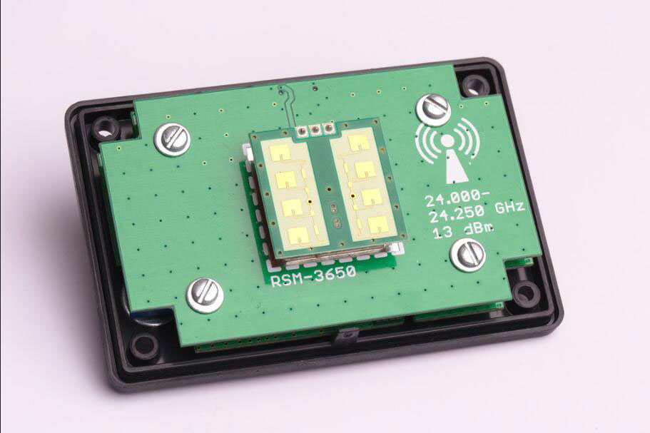
A radar module
Source: Flickr
Pulse Repetition Frequency
Radar signal delivery should be at every clock cycle with an appropriate delay interval between the clock cycles. Ideally, the device should receive the signal's echo before transmitting the next pulse.
Likewise, a radar PCB operates similarly, sending out periodic signals that form a wave of narrow rectangular pulses.
The delay between two clock pulses forms the pulse repetition time. With that in mind, pulse repetition frequency is the inverse of pulse repetition time. It defines the number of times the radar PCB sends out the signal.
Maximum Unambiguous Range
Each clock pulse should transmit a signal. However, you can only receive the echo for the current clock pulse after the following one if the interval between the two is short.
But you will note that the target's range is shorter than it should be. Therefore, you must choose the delay between the intervals wisely.
Ideally, you should receive the echo for the current clock pulse before the next one goes out. This way, the signals will give you a clear picture of the object's actual range, the maximum unambiguous range.
Minimum Range
Compared to the range, the minimum coverage is when the echo takes to get to the antenna after the first pulse width transmission.
Types Of Radar PCB
There are five types of radar PCBs. They include:
Doppler Radar PCB
As the name suggests, this type uses the Doppler effect to determine the data speed for objects within a specific distance.
It sends electromagnetic signals to the object then measures how the target affects the echo's signal frequency.
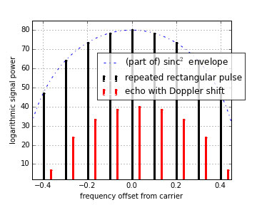
The Doppler spectrum. Note the repeated pulse spectrum
Source: Wikimedia Commons
It is possible to determine an object's velocity with the radar as the reference with the measurement and adjustment.
Monopulse Radar PCB
Monopulse radar PCBs contrast the received signal using a specific pulse by comparing the signal's characteristics as previously observed.
The most common type is the conical scanning radar circuit. It checks the results of the two methods to measure the object's position directly.
Passive Radar PCB
A passive radar PCB is a detection device that processes ambient illumination information. After that, it assists in pursuing targets.
Weather Radar PCB
Wind and weather detection is critical in today's world, and weather radar PCBs help with that by using radio frequency signals. However, there is a tradeoff between precipitation reflection due to the atmospheric moisture and attenuation.
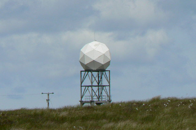
A weather radar station
Source: Wikimedia Commons
Similarly, you can use a weather radar that features Doppler shifts to measure wind speed and dual-polarization for determining the type of rainfall.
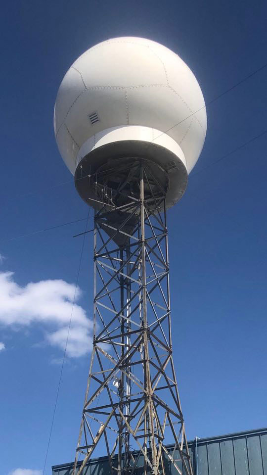
A Doppler radar at Huntsville International Airport
Source: Wikimedia Commons
Pulsed Radar PCBA
Lastly, this PCB type shoots high-frequency, high-intensity pulses at the target, then waits for the bounce-back signal before firing again.
To clarify, the repetitive firing frequency determines the radar PCB's range and resolution using the Doppler shift technique. This technique senses moving objects from the echoed signal in the following manner:
When bounced back, signals from static objects are in phase and cancel out.
When Pulses from moving objects have phase differences.
What is a Millimeter-Wave Radar PCBA Technology?
A millimeter-wave radar PCB is a critical component of ADAS (Advanced Driver Assistance Systems) for running an autopilot vehicle. However, it requires multiple parts to run, including materials capable of handling 77GHz millimeter-wave radar and higher.
Indeed, these 77GHzmm-wave radar PCBs have different construction material requirements than those operating at microwave and lower radio frequencies.
The reason is that the 77GHzmm-wave radar system module produces a shorter wavelength. Therefore, it needs thin circuit materials placed independently of the circuit design's transmission line architecture.
What is an ADAS Radar PCB?
In short, ADAS (Advanced Driver Assistance System) is an automotive safety system. It gathers data from the environmental conditions inside and outside the vehicle for object detection.
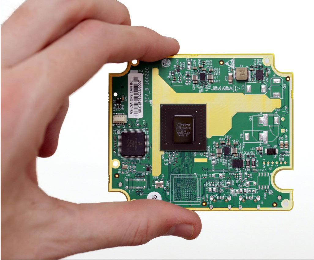
An automotive-grade 60GHz radar sensor for 4D imaging
Source: Wikimedia Commons
To clarify, the active safety system operates at millimeter-wave frequencies. Also, it uses various automotive radar sensors to identify and detect static or dynamic objects.
Indeed, the 77GHzmm-wave radar sensor has proven effective in automotive applications over time. Additionally, it plays a vital role in developing advanced driving assistance algorithms for self-driving vehicles.
Where Do You Find Radar PCBs?
Nautical maps, missile guiding, air defense, and enemy identification systems use radar PCBs for enhanced precision.
Military Use
Nautical maps, missile guiding, air defense, and enemy identification systems use radar PCBs for enhanced precision.
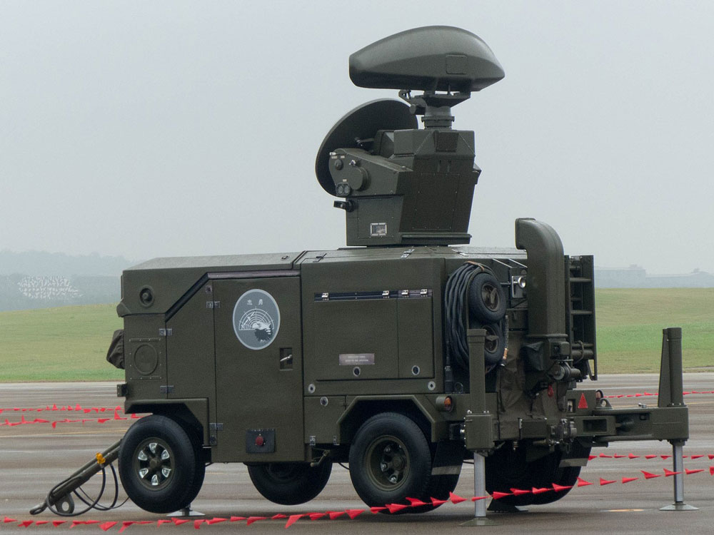
Skyguard radar display
Source: Wikimedia Commons
Controlling Air Traffic
Radar PCBs also come in handy in air surveillance equipment to help pinpoint aircraft positions close to ground vehicles and airports. Additionally, they help aircraft to land safely in bad weather.
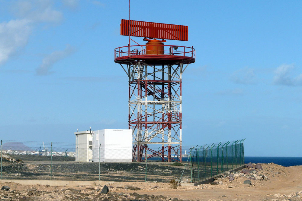
Air traffic control radar
Source: Wikimedia Commons
Remote Sensing
Similarly, navigation on the sea requires sensitive remote sensing equipment containing radar PCBs to help detect icebergs and sea vessels.
Ground Traffic Control
Like air traffic control, ground traffic control systems also need radar PCBs to manage traffic, control congestion, and monitor vehicle speeds.
A radar speed gun
Source: Wikimedia Commons
Space Application
Similarly, radar PCBs allow for safe navigation and landing of spaceships. Also, they help in tracking and monitoring satellites, planets, meteors, etc.
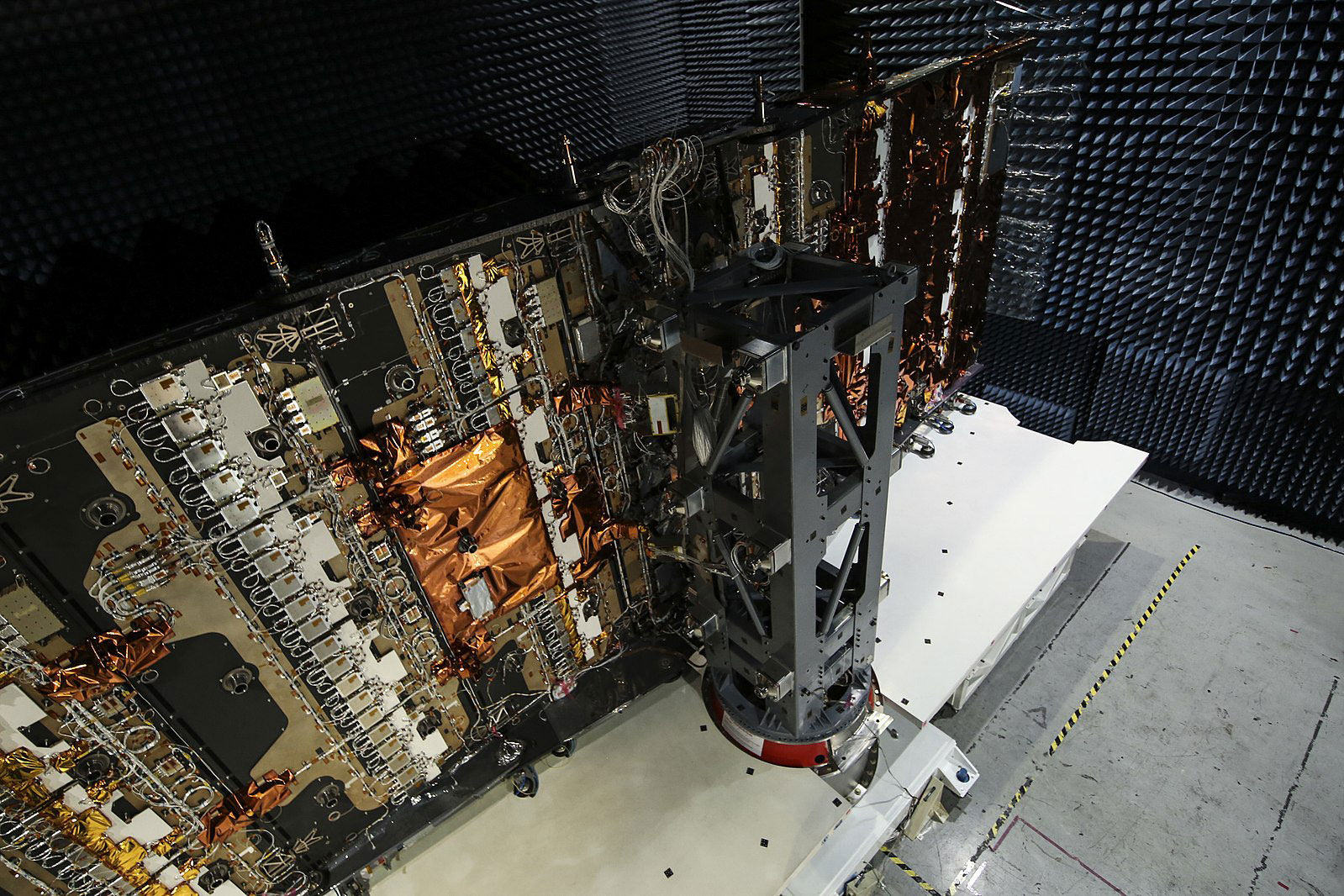
A satellite radar antenna
Source: Wikimedia Commons
Other applications include the following: automatic door openers, fire & trespassing alarms, intelligent lights, level meters, and autonomous driving.
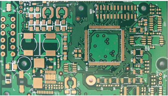
Materials Used For Radar PCBA
Manufacturers use two primary materials to make these PCBs:
Epoxy-Based
When a hydrocarbon resin matrix mixes with inorganic fillers and woven glass, it forms epoxy-based materials. This combination reduces the oxidation process while allowing low-profile copper film usage.
Polytetrafluoroethylene (PTFE)
PTFE is a synthetic fluoropolymer commonly used in either single, double-sided, or multi-layer boards with few layers. You can use the high-frequency circuit material with either woven glass or inorganic fillers for fabrication.
Advantages of Radar PCBs
Radar PCB signals can penetrate clouds and materials like rubber.
The radar PCB circuitry can determine an object's velocity, distance, and position when in motion.
Signals/pulses from a radar PCB don't need a medium (wire) for transmission because they can travel through space, water, and air.
The PCB operates at a high frequency to hold large amounts of data.
Signals from a radar PCB can cover large areas without requiring extra costs.
Design Steps In Radar PCBs
Fabricating a radar PCB involves the following steps:
Conceptualization
Conceptualization enables you to determine the circuit board's intended use. Remember, you can apply a radar PCB in different areas, like automotive applications (like the millimeter-wave applications), industrial applications, etc.
Likewise, consider the operating temperature, component population, board size, and other features.
Schematics
Next is drawing a schematic diagram, which includes all the component details and helps develop the bill of materials.
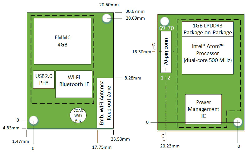
Creation of Block Diagram
The third is the creation of a block diagram. A radar PCB block diagram describes the board architecture & dimensions and illustrates areas for attaching components and other features.
A PCB block diagram
Source: Wikimedia Commons
Manufacturing Process
Manufacturing involves the actual radar PCBA fabrication, and you should consider factors like the stack up and material.
Component Placement
When placing the electronic components (surface mount technology, thru-hole, etc.), consider the position, density, order of positioning, the routing process, and circuit priority.
Efficient positioning by keeping the components close and ensuring the traces are short minimizes circuit loss.
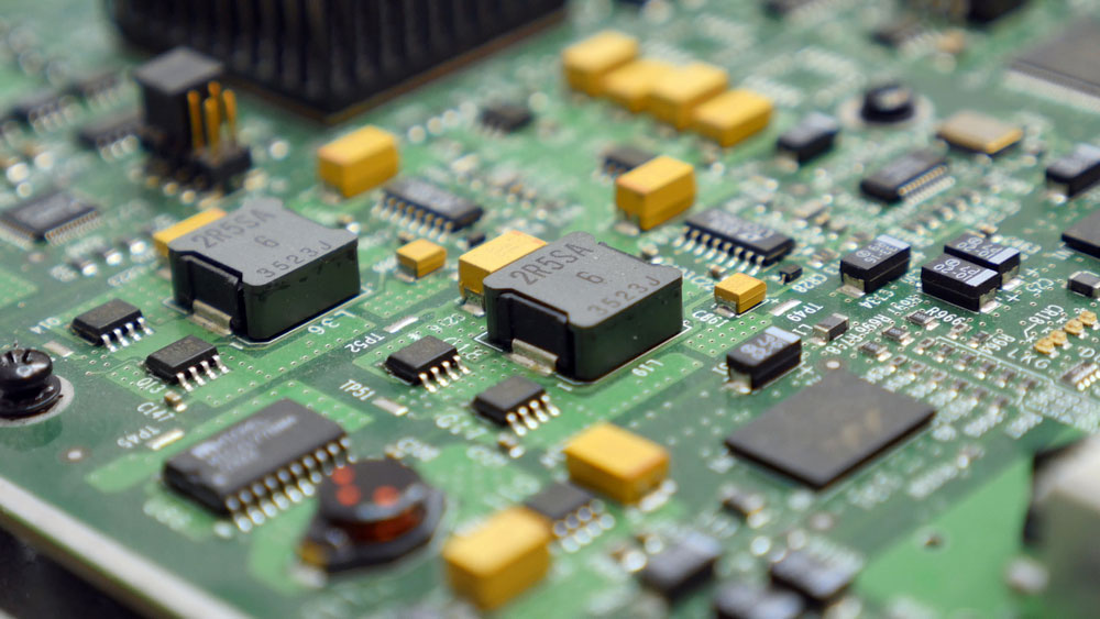
Components in a PCB
Circuit Routing
Circuit routing involves connecting a radar PCBA active components as per their priority. As a general rule of thumb, you should begin with the most delicate circuitry then the rest to avoid interference.
Common Types of Radar PCBA Failure Analysis Tests
Cross Sectioning
Cross sectioning is a destructive testing sequence. That is to say; it involves the precise separation and removal of the relevant electronic component from the radar PCBA. The process comes in handy when determining defects in these areas:
Component defects
Raw materials evaluation
Processing issues caused by reflow soldering
Shorts or opens
Failures resulting from thermomechanical forces
Solderability Examination
Incorrect solder mask application and oxidation are the most common causes of radar PCBA failure. Thus, solderability examination is a crucial testing procedure.
The process checks the strength and quality of the solder wetting to simulate the solder contact. Hence, it is ideal for PCBA coating, solder & flux evaluation, quality control, and benchmarking.
Radar PCBA Contamination Testing
Even though radar PCBA manufacturing and assembly occur in clean environments, contamination might occur. A contamination test uses the following methods and elements to prevent infections.
Hot air leveling fluxes
Water-soluble soldering
Electrolytic solutions
Copper etching liquid
Scanning Electron Microscopy
Scanning electron microscopy is one of the fastest and most precise testing procedures. Therefore, it is ideal for checking defects, flaws, and issues relating to assembly & soldering.
It uses a visibly lit, high-powered microscope to detect poor construction and reveal defects in specific cross-sections.
Also, you can use this method to study the metallization, quality, and integrity of the semiconductor die. Scanning electron microscopy can check the tiniest flaws, just a few nanometers broad.
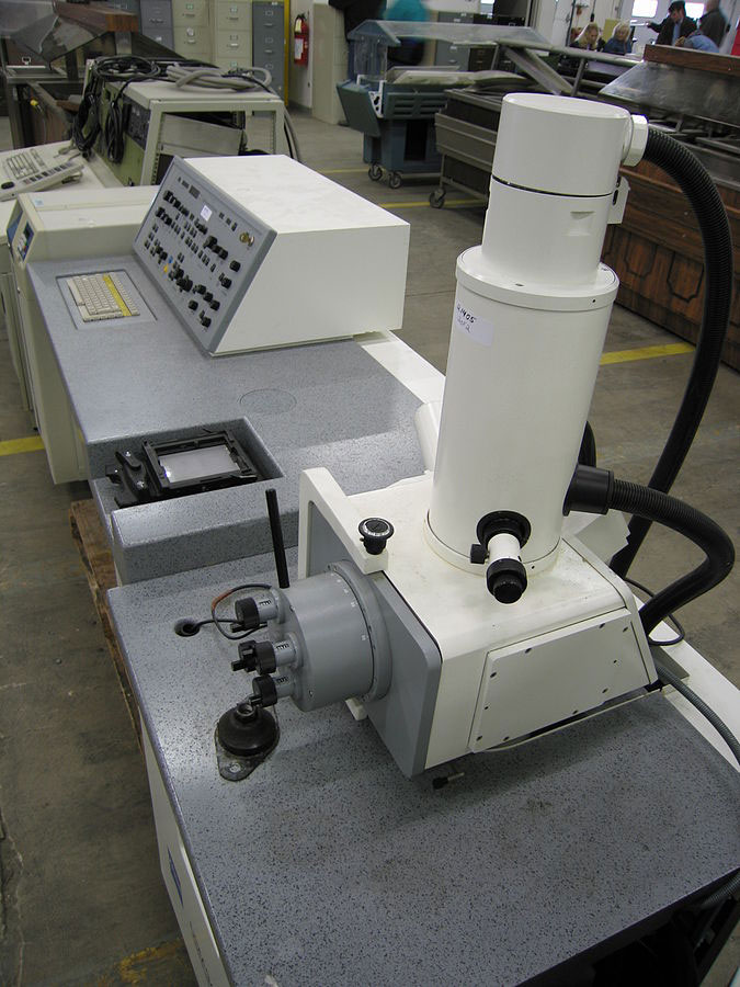
Scanning Electron Microscope
Source: Wikimedia Commons.
X-ray Examination
There are three types of X-ray examinations: essential film, real-time, and 3-dimensional. Each technique highlights concealed components and those with hidden joints in a non-destructive way.
X-rays allow interior inspection of the following: internal wire dress, sealing lid voids, excessive, insufficient, or poor solder, die-attach quality, interior particles, and trace integrity of the substrate/printing wiring board.
Summary
As you can see, radar PCBs are critical in modern and emerging technologies, especially as we enter into the era of autonomous cars. Therefore, if you need one for your project or have any questions, contact us for more details.
Comment on this article here
-
No comment

Ripple
Hi everyone, I'm Ripple, Sales Director of KFPCBA Tech Ltd. If you are looking for a one-stop PCB and PCB assembly manufacturer in China, KFPCBA is your best choice! Please feel free to contact our team! Thanks!
Contact me now
Relevant content you may be interested in
Related articles


