


 tel:+86-18825224069
 email:
 address:201, Factory 6, Longhui Industrial Park, Fuqiao 3rd District, Xinhe Community, Fuhai Street, Baoan District, Shenzhen china
How to Use PCB Prototype Board? Development to Testing
Release date:2022-08-11 10:17:25 Number of views:0
Although the PCB design process can be split in many ways, it is best viewed as having two basic phases: prototyping and product development.
Prototyping occurs at the earliest stages of design and involves a single engineer working on how to define a certain system or application. The experimental nature of this phase is fundamental to being able to develop hardware that meets specifications.
Once the design is validated, it can be passed to later stages of the design process (i.e. product development). The ultimate goal of the prototyping phase is to obtain a successful product that is accurate, efficient, and meets specifications. You want to achieve this with as few prototype iterations as possible to maximize time and resources.
Product Development of PCB Prototype
Product development is about getting the PCB ready for the final application. The prototype has met the design specifications (filtering, amplification, acquisition, measurement, etc.) and it is now time to take the design and implement it using best design practices.
Most companies have layout experts and are involved in product development. During this design phase, you are developing for manufacturing, so focus on increasing product yield and reducing manufacturing duplication.
Prototype PCb board in practice
Let's go back to the example from the earlier animation. The circuit consisted of a battery, a resistor, and a diode. The scheme is as follows:
Now let's transfer it to the PCb board. At the outset, it is worth noting that this system can be assembled into many different possibilities. This is just one example!
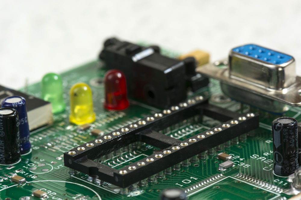
Let's start with placing the diode, remembering about the polarity.
Step 1: The cathode, i.e. the shorter leg (at the cut part of the housing), must be placed in the blue power rail. Its other leg can be plugged into any place on the board.
Step 2: Add a resistor; one lead must hit the same plate as the anode of the diode. The second one is placed elsewhere (here, on the other side of the tile).
Step 3: Connect the resistor lead to the positive power line (with a short wire).
Step 4: Connect the 9V battery - the diode is on!
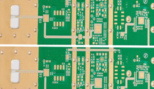
Across many varieties - from porous phenolic prototype boards to glass and plated through holes - PCB prototype circuit boards are characterized by providing a non-conductive environment for electronic components, electronic pathways, electronic tracks, and more. These single- or double-sided PCBs make circuit fabrication cheap and fast, eliminating many complex wiring methods.
Most Common Material Used in PCB Prototype
The most commonly used material for making PCBs is flame retardant epoxy glass cloth laminate (FR-4), which is an eight-layer glass fiber [VP1] material, a multi-functional high-pressure thermosetting plastic laminate grade material with high resistance to compressive strength.
This material has very low water absorption and can be used in both dry and wet conditions. Based on the excellent electrical insulation properties of this material under various conditions, it can be used in a wide range of applications and is the main material for manufacturing rigid PCBs.
In view of the good compressive strength, suitable cost, and flame retardant properties of FR-4, it is also commonly used to produce relays, switches, gaskets, transformers, busbars, etc.
Currently, printed circuit boards are widely used in the design of radio electronic devices and systems. The printed circuit board is designed for electrical and mechanical connection of various electronic
Components in PCB Prototype
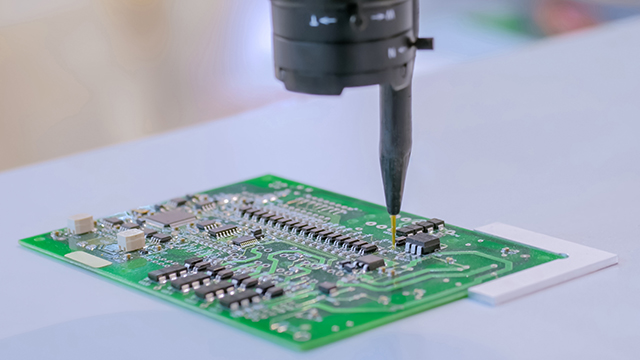
The electronic components on it are connected by their terminals to the elements of the conductive pattern, usually by soldering. Manual design of a printed circuit board containing tens and hundreds of components is a long and laborious process. Systems are used to speed up the design process and improve the quality of the finished product.
The PCB prototype board is designed to perform the main stages of designing single-layer and multilayer printed boards:
checking the created scheme for errors
creating a list of electrical circuit elements
placement of electronic components on the board
creation of an electrical circuit diagram
automatic tracing of a printed circuit board (creating a pattern of printed conductors)
the output of design documentation.
The proposed cycle of laboratory work allows students to master the main stages of designing a printed circuit board.
INTRODUCING THE PCB ARTIST DESIGN ENVIRONMENT
The purpose of the work: familiarity with the main elements of the package interface
1.1. Basic information
CAD PCB Artist contains two graphic editors:
Schematic Design Editor and PCB Design Editor, the Library Manager library program, as well as utility programs that perform utility functions. Much of the PCB design work
Requirements for the content of the report
The report must contain an algorithm for creating an electrical circuit (with commands) and a printout of the generated schema file.
The purpose of the work: is to create automatically electrical connections printed circuit board (perform automatic routing); optimize the drawing of printed conductors.\
Measures to ensure product quality
For the manufacture of printed circuit boards supplied in accordance with this International Standard, a quality assurance program shall be established and maintained at all times. The ISO 9000 series of standards on quality assurance systems is a system of standards that satisfies the requirements of this International Standard.
Testing of specific products should be carried out for compliance with specifications or as agreed between the manufacturer and the consumer.
The manufacturer shall have a process control system. The IPC-PC-90 series is a process control standards system.
The manufacturer shall have a process control system that meets the requirements of this standard.
Material Requirement in PCB Prototype Board
All materials used in the manufacture of printed circuit boards must meet the requirements of the relevant standards and documentation for their purchase.
The control of materials should consist of certification based on statistical testing of samples, confirming that all materials that make up the finished product comply with the documentation for the purchase of printed circuit boards.
The manufacturer is responsible for fulfilling all product control requirements following this standard. The user reserves the right to carry out any of the types of control listed in this standard if he considers them necessary to ensure the relevant requirements
Control, testing, and measuring equipment for testing in sufficient quantity, with the necessary accuracy and quality, must be installed and periodically verified per the technical regulations for equipment and instruments.
Rules for quality control of products
Quality control should be carried out using ready-made printed circuit boards or test coupons.
The quality of products for delivery should be verified by quality control as specified in the product specification. Delivery of inspected products should not be delayed due to delayed reliability testing.
Specifications for printed circuit boards supplied to the customer shall specify the criteria to be used to determine the type and number of test items and the frequency of their testing.
An inspection lot may be used to control product quality. The inspection lot must consist of printed circuit boards produced from the same base material, using the same design and manufacturing methods, under the same conditions, within a period of a maximum of one month and sent for testing at the same time.
Test Prototype PCB Board
The trace of controlled electrical circuits must be identical on all control lots of printed circuit boards. The quality of test boards or special test coupons should be comparable to the same boards produced using the same technology and on the same equipment.
Acceptance of products for delivery shall be based on the fact that they have been tested to meet all requirements set out in the printed circuit board specification.
When sampling is used, any defect on any of the samples recorded under the specifications for the printed circuit board will constitute a defect in the entire inspection lot, which must be dealt with by the requirements of this standard below.
If a lot is rejected, then the manufacturer must eliminate the defective printed circuit boards, i.e. carry out a 100% inspection of the batch, documented by the supplier's quality control system.
Defective printed circuit boards must be replaced according to the product quality assurance system.
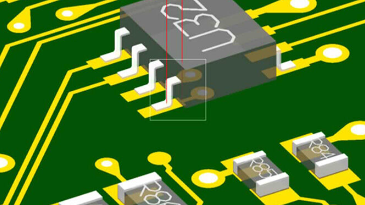
Distance between adjacent parallel interconnection lines
It must be at least 3.0 mm. The distance between individual UGOs should be not less than 2.0 mm.
6. All elements on the diagram must have a reference designation - a mandatory designation assigned to each part of the object and consisting of a letter and serial number. Letter designations of some electrical elements
Breadboards - When DIY, building, or just repairing, you often need to connect two pieces only temporarily. In such a situation, prototype boards will work best. We invite you to familiarize yourself with our assortment, which we have placed in the prototype boards category, including accessories for contact plates, contact plates, universal plates, and SMD-DIP adapters. Check what we have prepared for you and complete your perhaps first DIY kit.
Making your work easier
Prototype boards are very simple structures, a piece of plastic with metal rails inside, and yet they can make life and work extremely easy. This tool allows you to quickly and conveniently create prototypes of printed circuits without the need for soldering or etching. It is impossible to count the time saved and the work put into building projects.
There are various types of prototype boards available on the market, e.g. improvised, fabricated, soldered, or stripboards.
High-frequency circuits, in which the capacitance, resistance, and parasitic inductance determine relatively large widths and lengths of paths connecting elements, do not allow the use of universal boards.
The second criterion is often a matter of taste, often some electronics prefer to design directly on printed circuit boards, even if you have to repeat etching in case of errors.
Not only prototype boards
Prototype boards have many advantages and make it easier to assemble systems, but in our store in this category, you will also find accessories for them, universal boards, and SMD-DIP adapters. Our rich assortment will satisfy your needs, and if you have any questions or doubts, our technical department is at your disposal - write to us! We strive to ensure that the goods delivered to you are of the highest quality and at the most attractive prices.
Comment on this article here
-
No comment

Ripple
Hi everyone, I'm Ripple, Sales Director of KFPCBA Tech Ltd. If you are looking for a one-stop PCB and PCB assembly manufacturer in China, KFPCBA is your best choice! Please feel free to contact our team! Thanks!
Contact me now


