


 tel:+86-18825224069
 email:
 address:201, Factory 6, Longhui Industrial Park, Fuqiao 3rd District, Xinhe Community, Fuhai Street, Baoan District, Shenzhen china
PCB circuit board stack-up design should pay attention to these problems
Release date:2022-07-07 15:50:38 Number of views:0
What problems should be paid attention to in the design of PCB circuit board stack-up? Let professional engineers tell you below.
When doing stack-up design, be sure to follow two rules:
1. Each trace layer must have an adjacent reference layer (power or ground);
2. The adjacent main power plane and ground plane should maintain a minimum distance to provide larger coupling capacitance.
Let's take an example of two, four and six-layer boards to illustrate:

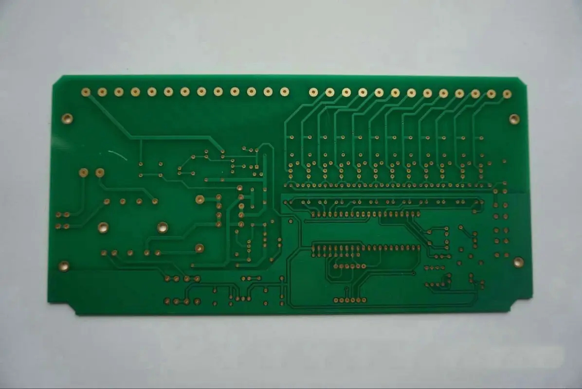
Lamination of single-sided and double-sided PCBs
For two-layer boards, controlling EMI radiation is mainly from the wiring and layout considerations.
The electromagnetic compatibility problem of single-layer boards and double-layer boards is becoming more and more prominent. The main reason for this phenomenon is that the signal loop area is too large, which not only produces strong electromagnetic radiation, but also makes the circuit sensitive to external interference. To improve the electromagnetic compatibility of the line, the easiest way is to reduce the loop area of the key signal; the key signal mainly refers to the signal that produces strong radiation and the signal that is sensitive to the outside world.
Single and double layers are usually used in low frequency analog designs below 10KHz:
1) The power supplies on the same layer are routed radially and the sum of the lengths of the lines is minimized;
2) When running the power and ground wires, they should be close to each other; lay a ground wire on the side of the key signal wire, and this ground wire should be as close to the signal wire as possible. In this way, a smaller loop area is formed and the sensitivity of differential mode radiation to external interference is reduced.
3) If it is a double-layer circuit board, you can lay a ground wire along the signal line on the other side of the circuit board, close to the signal line, and the line should be as wide as possible.
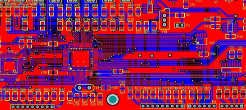
Lamination of four-layer boards
1. SIG-GND(PWR)-PWR (GND)-SIG;
2. GND-SIG(PWR)-SIG(PWR)-GND;
For the above two stack-up designs, the potential problem is for the traditional 1.6mm (62mil) board thickness. The layer spacing will become very large, which is not conducive to controlling impedance, interlayer coupling and shielding; especially, the large spacing between the power ground layers reduces the board capacitance and is not conducive to filtering noise.
The first solution is usually used when there are many chips on the board. This solution can get better SI performance, but it is not very good for EMI performance, which is mainly controlled by wiring and other details.
The second solution is usually used when the chip density on the board is low enough and there is enough area around the chip. In this scheme, the outer layers of the PCB are the ground layers, and the two middle layers are the signal/power layers. From an EMI control standpoint, this is the best 4-layer PCB structure available.
Main attention: The distance between the two middle layers of signal and power mixed layers should be widened, and the wiring direction should be vertical to avoid crosstalk; the area of the board should be properly controlled to reflect the 20H rule.

Lamination of six-layer boards
For the design with high chip density and high clock frequency, the design of 6-layer board should be considered. The recommended stacking method:
1.SIG-GND-SIG-PWR-GND-SIG;
This stacking scheme can achieve better signal integrity, the signal layer is adjacent to the ground layer, the power layer and the ground layer are paired, the impedance of each trace layer can be well controlled, and both ground layers are well absorption magnetic field lines.
2. GND-SIG-GND-PWR-SIG-GND;
This scheme is only suitable for the case where the device density is not very high. This kind of stack has all the advantages of the above stack, and the ground planes of the top and bottom layers are relatively complete, which can be used as a better shielding layer. Therefore, the EMI performance is better than the first solution.
Summary: Comparing the first scheme with the second scheme, the cost of the second scheme is greatly increased. Therefore, we usually choose the first solution when stacking.
Comment on this article here
-
No comment

Ripple
Hi everyone, I'm Ripple, Sales Director of KFPCBA Tech Ltd. If you are looking for a one-stop PCB and PCB assembly manufacturer in China, KFPCBA is your best choice! Please feel free to contact our team! Thanks!
Contact me now
Relevant content you may be interested in
Related articles


